Engine cylinder body compressing device

A technology of engine cylinder block and compression device, which is applied in the direction of workpiece clamping device and manufacturing tools, can solve the problems such as inability to achieve flat compression, achieve the effect of improving the flexibility of disassembly and assembly, and increasing the working range

Active Publication Date: 2018-12-11
GUANGXI YUCHAI MASCH CO LTD
View PDF7 Cites 1 Cited by
  • Summary
  • Abstract
  • Description
  • Claims
  • Application Information

AI Technical Summary

Problems solved by technology

When the engine is installed on the assembly line, it is necessary to compress the engine block, and now the engine block cannot be pressed flat

Method used


Image

  • Engine cylinder body compressing device
  • Engine cylinder body compressing device

Examples


Embodiment Construction

[0022] The present invention will be further described in detail below in combination with specific embodiments and with reference to the accompanying drawings. It should be emphasized that the following description is only exemplary and not intended to limit the scope of the invention and its application.

[0023] Non-limiting and non-exclusive embodiments will be described with reference to the following drawings, wherein like reference numerals refer to like parts unless specifically stated otherwise.

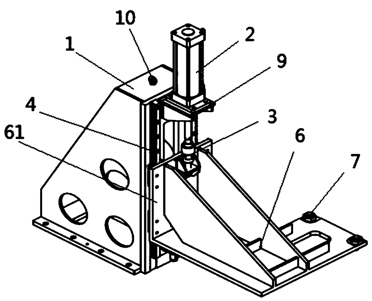
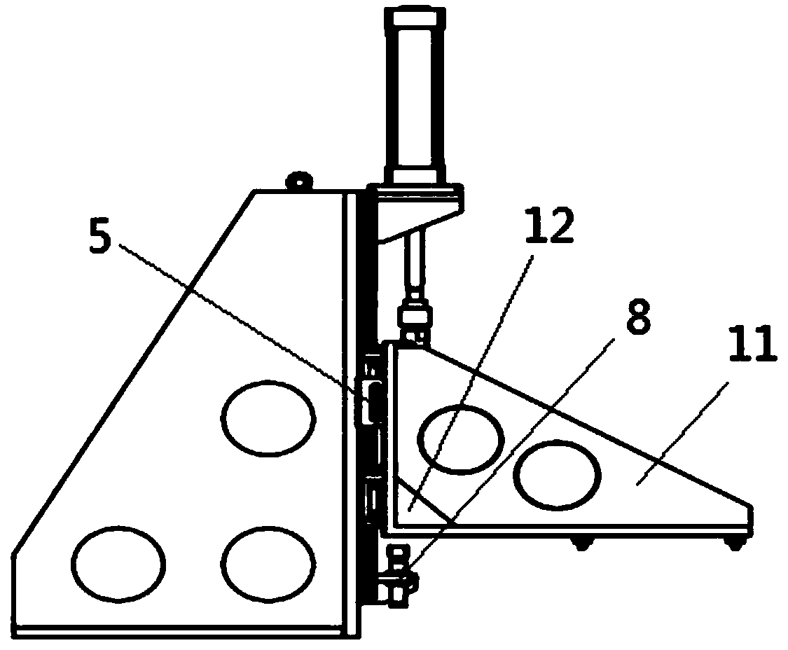
[0024] refer to Figure 1-2 The engine block compression device shown includes a fixed frame 1, a cylinder 2, a slide rail 4, a slider 5, a pressure plate, a positioning pin 7, a connector 3, a cylinder block compression buffer 8, and a connecting frame, The fixed frame 1 is surrounded by a plurality of flat plates; the front panel of the fixed frame 1 fixes the support frame 9 and the slide rail 4, the lower panel is provided with connecting holes, the side panels are wedg...


PUM


Abstract

The invention discloses an engine cylinder body compressing device which comprises a fixing frame, an air cylinder, a slide rail, sliders, a pressing plate and a positioning pin. An air cylinder supporting frame is arranged on the upper portion of the fixing frame and provided with a penetrating hole. The slide rails are fixed to the fixing frame and arranged on two sides of the supporting frame correspondingly in a vertically downward mode. The air cylinder is fixed to the supporting frame, and a guide rod of the air cylinder penetrates out of the penetrating hole of the supporting frame andis vertically downward. The pressing plate is composed of an L-shaped plate and a connecting plate, the connecting plate is perpendicularly fixed to the rear end of the L-shaped plate, and the plate surface of the connecting plate is slidably arranged on the slide rails through the sliders. The positioning pin is fixed to the front end of the L-shaped plate. The lower end of the guide rod of the air cylinder is connected with the upper portion of the connecting plate. The engine cylinder body compressing device has the advantages that the structure is simple, work is reliable, the compressingeffect on the plane of an engine is good, and interference with assembly accessories is avoided.

Description

technical field [0001] The invention relates to the technical field of engine assembly, in particular to an engine cylinder pressing device. Background technique [0002] When the engine is installed, it is necessary to transport the cylinder block for inspection and install parts, and the transport cylinder block needs to stop on the raceway for inspection and installation of parts. When the engine is installed on the assembly line, it is necessary to compress the engine block, but the compression of the engine block cannot achieve flat compression. [0003] The disclosure of the above background technical content is only used to assist in understanding the concept and technical solution of the present invention, and it does not necessarily belong to the prior art of this patent application. If there is no clear evidence that the above content has been disclosed on the filing date of this patent application In some cases, the above background technology should not be used ...

Claims


Application Information

Patent Timeline
Patent Type & Authority Applications(China)
IPC IPC(8): B25B11/02
CPCB25B11/02
Inventor 梁雄伟姚建东庞振华梁业苏思杰何壮华
Owner GUANGXI YUCHAI MASCH CO LTD
Why Eureka
Try Eureka