Image recording apparatus

a recording apparatus and image technology, applied in the direction of thin material processing, article separation, printing, etc., can solve the problems of insufficient conveying of recording medium, likely pulling of recording medium by force to exert an excessive load on the separate conveyance unit, etc., to achieve the effect of miniaturizing the image recording apparatus, facilitating the transfer of recording medium, and simplifying the structure of the image recording apparatus

Active Publication Date: 2008-10-14
BROTHER KOGYO KK
View PDF22 Cites 26 Cited by
  • Summary
  • Abstract
  • Description
  • Claims
  • Application Information

AI Technical Summary

Benefits of technology

[0006]Accordingly, the present invention has been made in an effort to solve the problems described above, and the invention provides an image recording apparatus, which can reliably convey a recording medium while accomplishing structural simplicity.
[0008]Since the passage for allowing the recording medium to move in the thickness direction of the recording medium is defined between the outer arcuate guide member and the inner arcuate guide member, freedom is provided in a posture of the recording medium, which is conveyed. Thus, it is possible to reliably convey the recording medium without using pinch rollers. As a result, since a structure of the image recording apparatus is simplified, it is possible to miniaturize the image recording apparatus and reduce a manufacturing cost.

Problems solved by technology

Therefore, in this type of image recording apparatus, if the conveyance unit including the pinch rollers and so forth is omitted for the sake of structural simplicity, when a pulling force is applied to the recording medium from the separate conveyance unit provided outside the passage, the recording medium is likely to be pulled by force to exert an excessive load to the separate conveyance unit, whereby the recording medium may be inadequately conveyed.

Method used


Image

  • Image recording apparatus
  • Image recording apparatus
  • Image recording apparatus

Examples


first embodiment

[0035]the present invention will be described with reference to FIGS. 1 through 12.

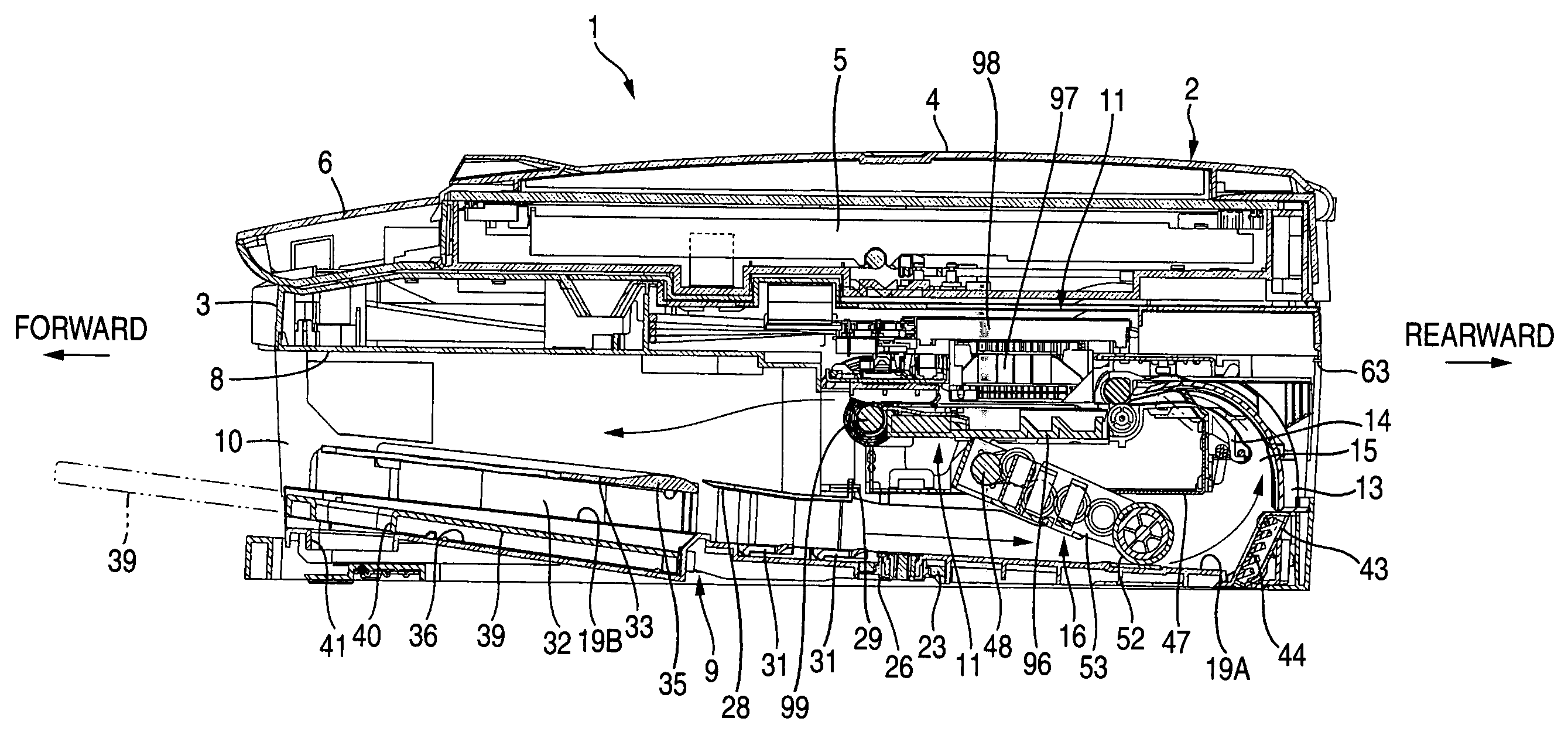
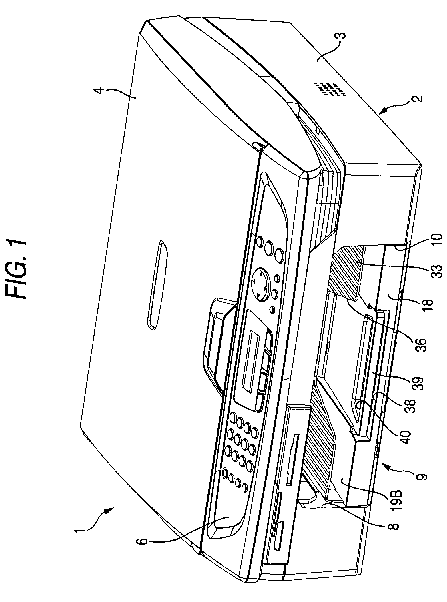
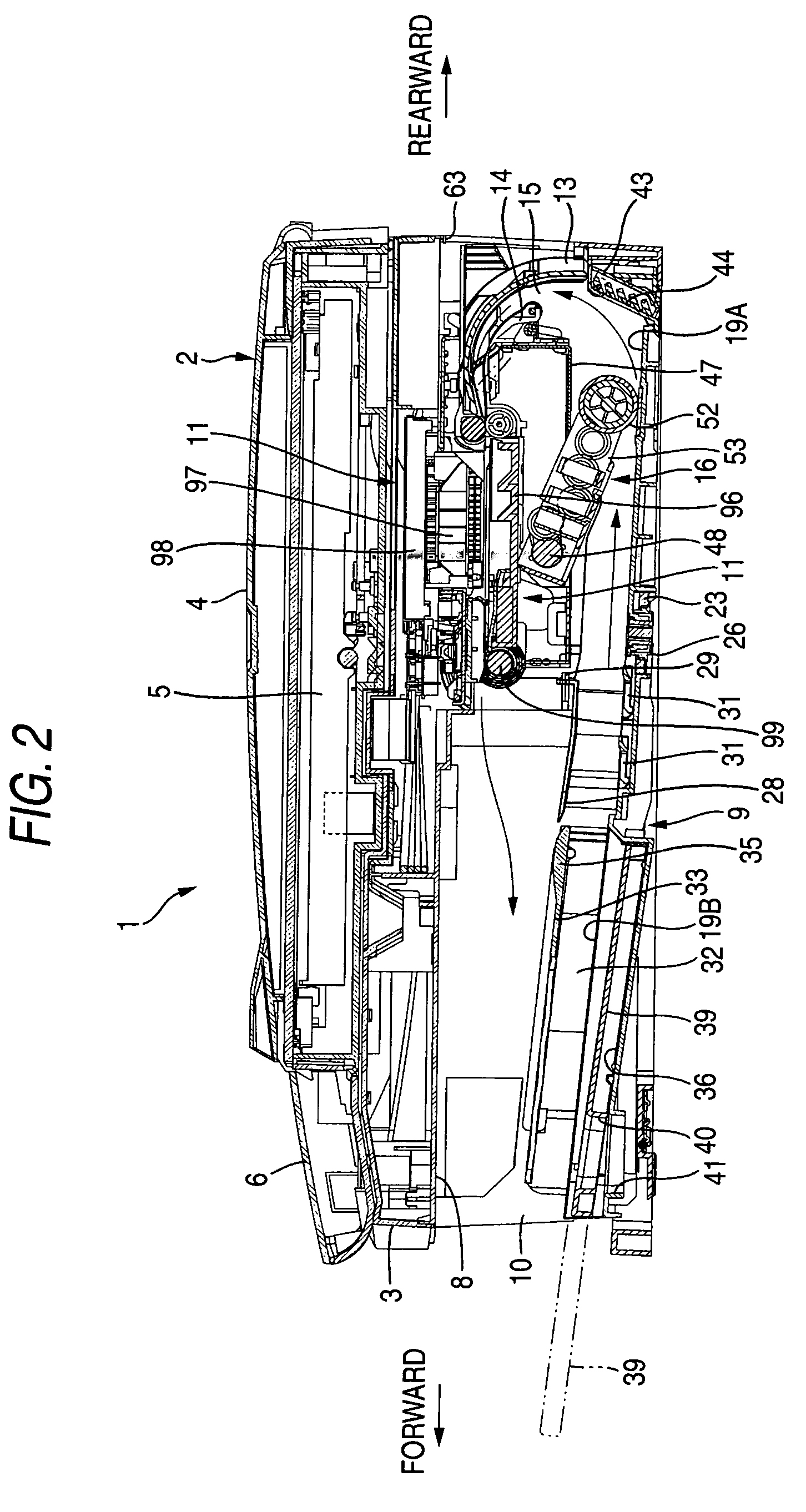
[0036]FIG. 1 is a perspective view illustrating an outer appearance of an image recording apparatus 1 in accordance with the first embodiment of the present invention. FIG. 2 is a sectional view of the image recording apparatus 1. In the following description, upward and downward directions will be determined based on FIG. 2. Also, in respect of forward and rearward directions, a direction facing the left side of FIG. 2 will be considered as the forward direction.

[0037]The image recoding apparatus 1 according to this first embodiment serves as a multifunction device, which has a facsimile function, a printer function, a copier function, and a scanner function. The image recording apparatus 1 includes a casing 2, which substantially has the shape of a box. When viewed from the top, the casing 2 defines a substantially square configuration having a side which is a size greater than a longer side of an A...


PUM


Abstract

An image recording apparatus includes an accommodation section, an image recording section, an outer arcuate guide member, an inner arcuate guide member, and a feeding section. Recording media are stacked on the accommodation section. The image recording section forms an image on a recording medium conveyed in a conveyance direction. The outer arcuate guide member connects in a U-shape the accommodation section with the image recording section. The outer arcuate guide member guides the recording medium from a downstream end portion of the accommodation section to an insertion port of the image recording section. The inner arcuate guide member is disposed to be separate from the outer arcuate guide member. A passage is defined between the outer arcuate guide member and the inner arcuate guide member. The passage allows the recording medium to displace in a thickness direction thereof.

Description

BACKGROUND OF THE INVENTION[0001]1. Field of the Invention[0002]The present invention relates to an image recording apparatus.[0003]2. Description of the Related Art[0004]U.S. Pat. No. 6,651,974 discloses an image recording apparatus such as a printer, a copying machine, or a facsimile machine in which an accommodation section for accommodating recording media such as papers, OHP sheets, etc. and an image recording section for recording an image on each of the recording media are arranged in a vertical direction and are connected with each other through a U-shaped passage so that each recording medium can be conveyed from the accommodation section through the passage to the image recording section. The U-shaped passage has a pair of curved guide members for positioning the recording medium from both sides in a thickness direction of the recording medium. In the middle of the U-shaped passage, there is disposed conveyance unit such as pinch rollers, which tightly sandwich the recordi...

Claims


Application Information

Patent Timeline
Patent Type & Authority Patents(United States)
IPC IPC(8): B41J11/58B65H3/06B65H3/66
CPCB65H3/0684B65H5/38B65H2404/513B65H2404/6111B65H2405/1136B65H2801/06B65H1/266B65H3/0669B65H3/56B65H2404/521B65H2404/54
Inventor TANAHASHI, NAOKAZUSHIOHARA, YUKIOWATANABE, YUSAKUNUKUI, KOSUKE
Owner BROTHER KOGYO KK
Why Eureka
Try Eureka