
Vaporizer device for an inhaler, in particular for an electronic cigarette product, and fabrication method

Active Publication Date: 2019-06-20
KÖRBER TECH GMBH
View PDF0 Cites 1 Cited by
  • Summary
  • Abstract
  • Description
  • Claims
  • Application Information

AI Technical Summary

Benefits of technology

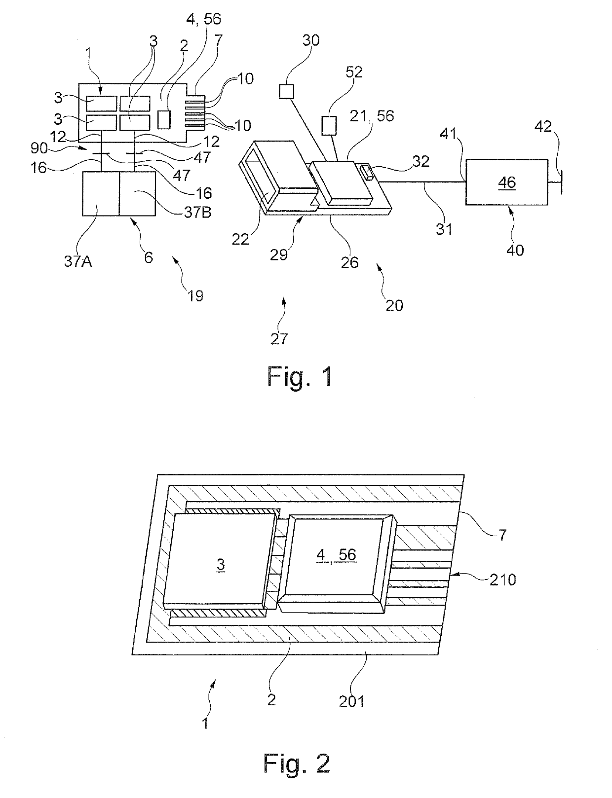
This patent is about a vaporizer device and its fabrication method that allow for cost-effective manufacturing while also improving the quality and intensity of the aerosol or vapor produced. The device has a flexible design that includes regions with different thicknesses to account for the device's structural mechanical and electrical circumstances. Additionally, the device has a capillary element that extends at least partially through the openings to ensure reliable conveyance of liquid independent of the orientation from the tank to the vaporizer.

Problems solved by technology

In the case of heating via a wire grid, also called a mesh, a non-homogeneous temperature field can develop over the vaporizer surface, because the heat output is namely substantially constant over the mesh surface, but the heat dissipation is very non-homogeneous due to the locally different subsequent conveyance of liquid and even local desiccation as the case may be.
However, since only one temperature averaged over the entire heater surface is recorded in this way, only very large local temperature increases can be detected based on desiccation.
In addition, a subsequent reduction in the heat output would also affect regions that are at the correct temperature and reduce the temperature there, and thereby reduce the quantity of vapor generated.
However, the silicon MEMS technology described there is relatively expensive.
In addition, the individual channels of the vaporizer chip are electrically connected to the corresponding regulating electronics, which leads an increased installation expense.

Method used


Image

  • Vaporizer device for an inhaler, in particular for an electronic cigarette product, and fabrication method
  • Vaporizer device for an inhaler, in particular for an electronic cigarette product, and fabrication method

Examples


embodiments

Embodiment 1

[0090]Vaporizer device (1) for an inhaler (27), in particular for an electronic cigarette product, comprising:[0091]an electrical vaporizer (3) having one or more heating elements (15) for vaporizing liquid supplied by the vaporizer (3),

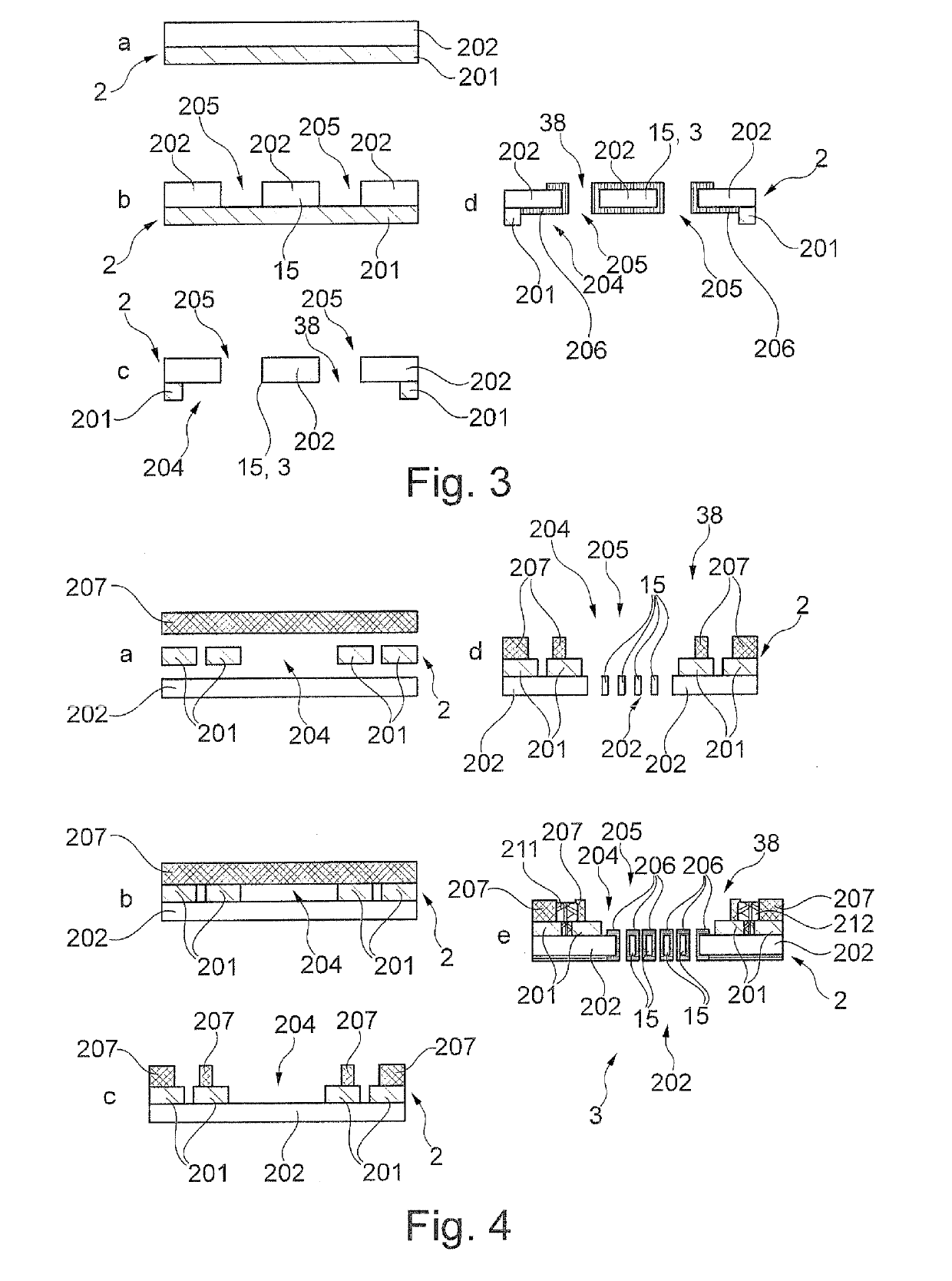
characterized in that[0092]a carrier (2) is formed of a layer system with a polymer film (201) and at least one metal film (202) in contact with the polymer film (201) in a planar manner,[0093]the polymer film (201) comprises at least one fluid permeable first opening (204),[0094]the metal film (202) comprises at least one fluid permeable second opening (205) communicating with the first opening (204), and[0095]the metal film (202) forms the heating elements (15), wherein the heating elements (15) are arranged delimiting the second opening (205).

embodiment 2

[0096]Vaporizer device according to embodiment 1, characterized in that the metal film (202) has a passivating coating (206) at least on the sections not in contact with the polymer film (201) and / or the heating elements (15).

[0097]Embodiment 3. Vaporizer device according to one of the preceding embodiments, characterized in that the carrier (2) comprises a metal layer (207), and the metal layer (207) is in contact with the polymer film (201) on the side opposite from the metal film (202).

embodiment 4

[0098]Vaporizer device according to one of the preceding embodiments, characterized in that the carrier (2) comprises at least one contact (211, 212) for making electrical contact with an electronic component (4, 56).


PUM


Abstract

A vaporizer device for an inhaler, in particular for an electronic cigarette product, comprises an electrical vaporizer having one or more heating elements for vaporizing liquid supplied by the vaporizer. The vaporizer device is characterized in that a carrier is formed of a layer system with a polymer film and at least one metal film in contact with the polymer film in a planar manner, the polymer film comprises at least one fluid permeable opening, the metal film comprises at least one fluid permeable second opening communicating with the first opening, and the metal film forms the heating elements, wherein the heating elements are arranged delimiting the second opening.

Description

CROSS REFERENCE TO A RELATED APPLICATION[0001]This application claims priority under 35 U.S.C. § 119(e) of German Patent Application No. DE 10 2017 130 501.7, filed Dec. 19, 2017, which is incorporated herein by reference in its entirety.FIELD OF THE INVENTION[0002]The present invention relates to a vaporizer device for an inhaler, in particular for an electronic cigarette product, comprising an electrical vaporizer having one or more heating elements for vaporizing liquid supplied by the vaporizer. The invention relates further to a corresponding inhaler, a vaporizer unit and a cartridge for an inhaler as well as a method for fabricating a vaporizer device.BACKGROUND OF THE INVENTION[0003]At present between one and up to five vaporizer heads based on the wick-coil principle are used in current electronic cigarettes. The planar vaporization of liquid directly at the liquid surface is also another approach in addition to common wick-coil E-cigarettes; see, for example, Patent Applica...

Claims


Application Information

Patent Timeline
IPC IPC(8): A24F47/00A24F40/10A24F40/46A24F40/70
CPCA24F47/008A24F40/46A24F40/10A24F40/70A24F40/40A24F40/51A24F40/57A24B15/167A61M15/06
Inventor RATH, SONALIGHANAM, MUHANNADJAKLIN, JANPELZ, UWEWOIAS, PETERGOLDSCHMIDTBOING, FRANK
Owner KÖRBER TECH GMBH
Learn More