Brewing apparatus and method for operating a brewing apparatus
a technology of brewing apparatus and brewing chamber, which is applied in beverage vessels, household appliances, kitchen equipment, etc., can solve the problems of high complexity and high cost, and achieve the effect of improving the sealing of the brewing chamber during the brewing operation and cost-effective production of the brewing apparatus
- Summary
- Abstract
- Description
- Claims
- Application Information
AI Technical Summary
Benefits of technology
Problems solved by technology
Method used
Image
Examples
first embodiment
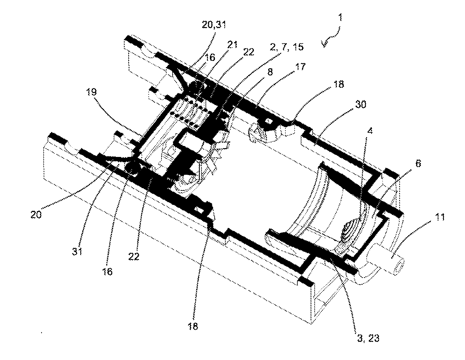
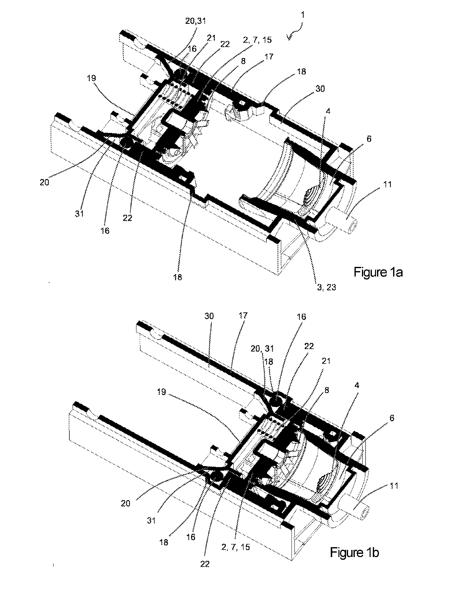
[0043]In FIGS. 1a to 1b schematic sectional views of a brewing apparatus 1 according to the present invention are illustrated. The brewing apparatus 1 displays a first brewing chamber element 2 and a second brewing chamber element 3 which are spaced apart from each other in a loading position, such that a portion capsule 4 which is filled with a beverage substance (not illustrated) can be introduced in the loading direction. The first brewing chamber element 2 is movable in the axial direction 5, in order to form a substantially closed brewing chamber 6 with the second brewing chamber element 3 which is provided for receiving the portion capsule 4 (see FIG. 2). The first brewing chamber element 2 comprises a perforating element 7 having perforating tips 8 for perforating the capsule lid 9, and a water infeed duct (not illustrated) for injecting an extraction fluid into the portion capsule 4 during the brewing operation. The second brewing chamber element 3 comprises a further perfor...
second embodiment
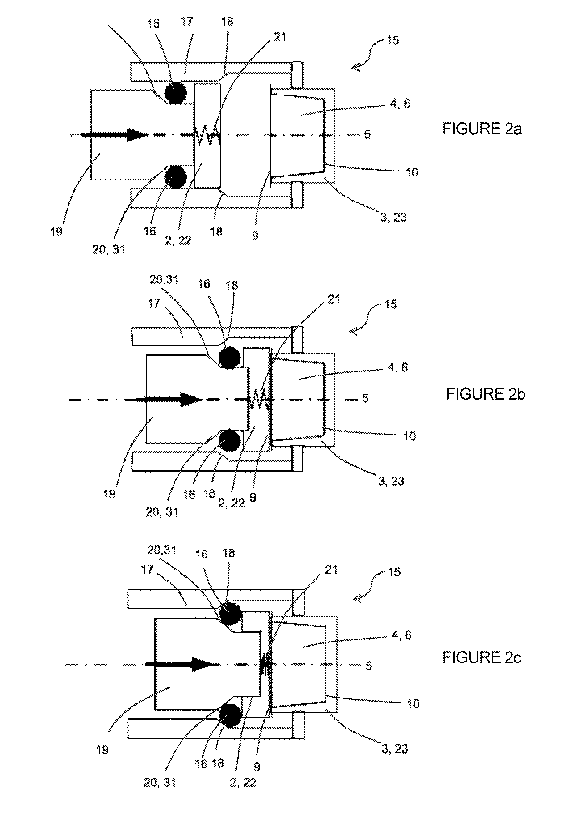
[0052]In FIGS. 2a to 2g schematic views of a locking mechanism 15 according to the present invention are illustrated, wherein the individual steps for locking and unlocking the locking mechanism 15 will be explained in more detail.
[0053]FIG. 2a depicts a brewing apparatus 1 which is situated in the loading position, having a locking mechanism 15 in the releasing position. The latch 16 here is displaceably disposed along the axial direction 5, between a first wall part 17, displaying a first chamfer 18, and a first brewing chamber element 2, displaying a displacing element 19 having a second chamfer 2, a retaining element 22, and a return spring 21, which elastically connects the retaining element 22 to the displacing element 19. A portion capsule 4 here is positioned in a receiving element 23, which is provided for receiving the portion capsule 4 and is designed in a bell-shaped manner, of a second brewing chamber element 3 which is fixedly connected to the wall part 17. On account ...
seventh embodiment
[0089]In FIGS. 8a to 8b, schematic views of a locking mechanism 15 according to the present invention are illustrated. Here, a first brewing chamber element 2 is illustrated in a side view. Here, the portion capsule 4 bears on a retaining arm 22′; which here is fixedly connected to the retaining element 22. Here, the first brewing chamber element 2 displays a holding apparatus 40. The holding apparatus 40 here in particular comprises a further retaining arm 41 which is provided for holding the portion capsule 4 in its position which is assumed after charging the brewing apparatus 1. Here, the holding apparatus 40 is disposed so as to be movable in relation to the retaining element 22 by way of a return spring 22″ which is fastened on the retaining element 22. Here, in an exemplary manner, a movement of the holding apparatus 40 along a direction of movement 100 which is parallel with the axial direction 5, relative to the retaining element 22, is indicated by an arrow 100, wherein th...
PUM
 Abstract
Description
Claims
Application Information
 - R&D
- Intellectual Property
- Life Sciences
- Materials
- Tech Scout
- Unparalleled Data Quality
- Higher Quality Content
- 60% Fewer Hallucinations
Browse by: Latest US Patents, China's latest patents, Technical Efficacy Thesaurus, Application Domain, Technology Topic, Popular Technical Reports.
© 2025 PatSnap. All rights reserved.Legal|Privacy policy|Modern Slavery Act Transparency Statement|Sitemap|About US| Contact US: help@patsnap.com


