Electric machine, particularly a brushless direct current motor

Inactive Publication Date: 2006-05-25
MINEBEA CO LTD
View PDF8 Cites 36 Cited by
  • Summary
  • Abstract
  • Description
  • Claims
  • Application Information

AI Technical Summary

Benefits of technology

[0013] It is an object of the invention to provide an electric machine, particularly a brushless DC motor, th

Problems solved by technology

The extension of the rotor arrangement 12, 14 in an axial direction gives rise to non-negligible extra costs for ferromagnetic and magnetic material as well as certain additional manufacturing work and expense.
The disadvantage of this version is that the axial stray field of the permanent magnets 14 is significantly weaker than the radial stray field, which means that the Hall e

Method used


Image

  • Electric machine, particularly a brushless direct current motor
  • Electric machine, particularly a brushless direct current motor
  • Electric machine, particularly a brushless direct current motor

Examples


Embodiment Construction

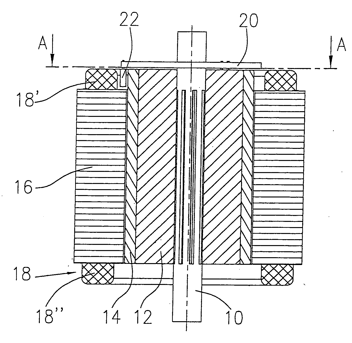
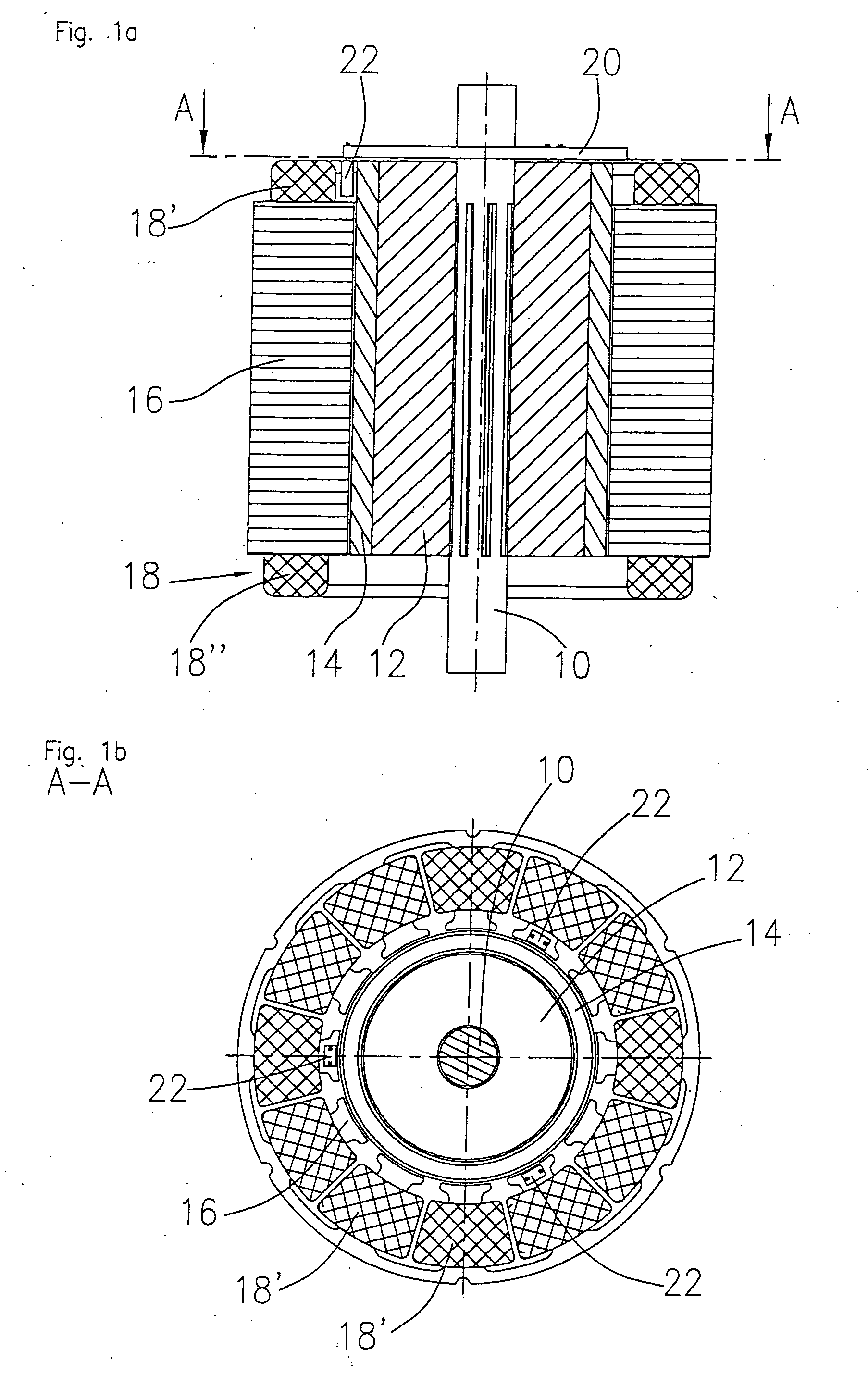
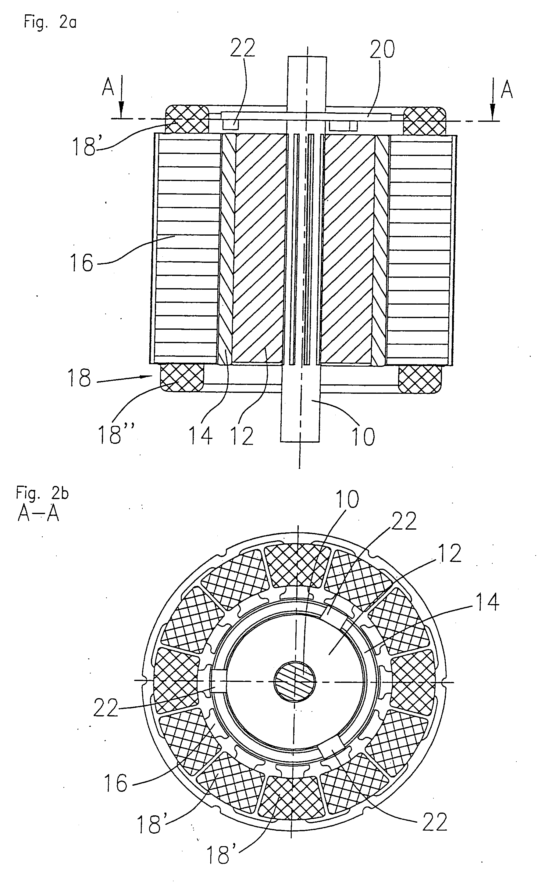
[0036] As shown in FIGS. 4a to 4c, the electric motor according to the invention, which is preferably designed as a brushless DC motor, comprises a shaft 30 that carries a rotor arrangement 32. The rotor arrangement 32 is coaxially inserted into a stator arrangement which is basically constructed in the same way as in the prior art. That means that the stator arrangement comprises a stator body 36 and windings 38. The stator body 36 can be built up of a stack of stamped laminations that forms a stator back yoke ring having stator poles that carry windings 38, as can best be seen from FIG. 4c. The rotor arrangement 32 comprises a rotor body 40 that has spoke-like recesses 42 into which the permanent magnets are inserted. In the preferred embodiment, the recesses 42 to receive the permanent magnets are bridged in pairs by a cutout 46. This cutout 46 is used to suppress radial stray flux in the interior of the rotor arrangement 32 towards the shaft 30.

[0037] As is apparent when FIGS. ...


PUM


Abstract

An electric machine, in particular a brushless DC motor, having a stator arrangement and a rotor arrangement that are arranged coaxially with respect to one another, the rotor arrangement having a rotor body and permanent magnets embedded in the rotor body, at least one magnetic sensor for the purpose of measuring the rotational position of the rotor body being disposed at an end face of the rotor body and being located directly opposite this end face

Description

FIELD OF THE INVENTION [0001] The invention relates to an electric machine, and in particular a brushless direct current motor comprising a stator arrangement and a rotor arrangement that are aligned coaxially with respect to one another, the rotor arrangement having a rotor body and permanent magnets embedded in the rotor body. BACKGROUND OF THE INVENTION [0002] A preferred field of application for the invention is in brushless DC motors and other permanent magnet motors that can be configured as inner rotor motors or as outer rotor motors. Electric motors in which the invention finds application have a rotor body that is mounted onto a shaft, permanent magnets being embedded in the rotor body, preferably in a spoke-like arrangement. The motors further comprise a stator arrangement that generally consists of a number of stacked metal laminations which form an annular stator back yoke from which stator teeth extend either radially inwards or radially outwards. The stator teeth form ...

Claims


Application Information

Patent Timeline
IPC IPC(8): H02K11/00H02K23/66
CPCH02K5/128H02K29/08
Inventor HAUGER, WILLIGANTER, HELMUTHANS, HELMUT
Owner MINEBEA CO LTD
Why Eureka
Try Eureka