Balancing Voltage for a Multi-Cell Battery System

a battery system and multi-cell technology, applied in the direction of battery/fuel cell control arrangement, electric devices, transportation and packaging, etc., can solve the problems of destroying the cell completely, affecting the expected lifetime of the cell, and affecting the ability of the battery to be replaced

Active Publication Date: 2012-06-07
VOLKSWAGEN AG +1
View PDF2 Cites 52 Cited by
  • Summary
  • Abstract
  • Description
  • Claims
  • Application Information

AI Technical Summary

Benefits of technology

[0014]Example embodiments of the present invention provide an improve

Problems solved by technology

In use, the cells are usually not completely discharged or charged because this would harm the expected lifetime of the cells or even destroy the cells completely.
More importantly, continuing to charge a cell that is completely full or to discharge a cell past its recommended minimum voltage may damage the cell.
It would be too difficult to replace single cells in the field.
Usually charged batteries continuously lose a small amount of their stored energy over time by unwanted internal leakage.
In this situation, it is likely that there are groups of parallel batteries which are not empty yet but which can not be discharged further because one parallel group of batteries in a module has reached its

Method used


Image

  • Balancing Voltage for a Multi-Cell Battery System
  • Balancing Voltage for a Multi-Cell Battery System
  • Balancing Voltage for a Multi-Cell Battery System

Examples


Embodiment Construction

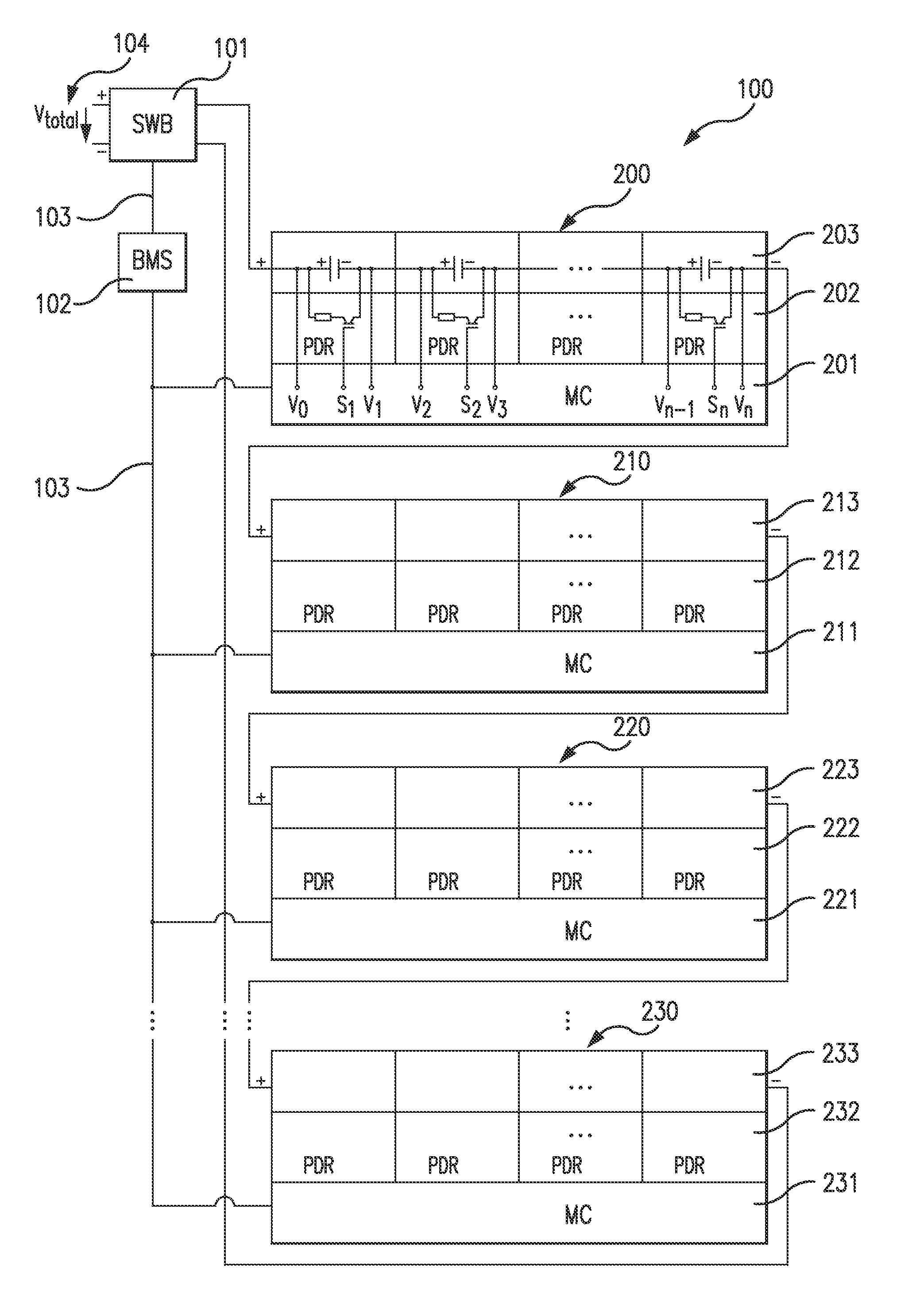
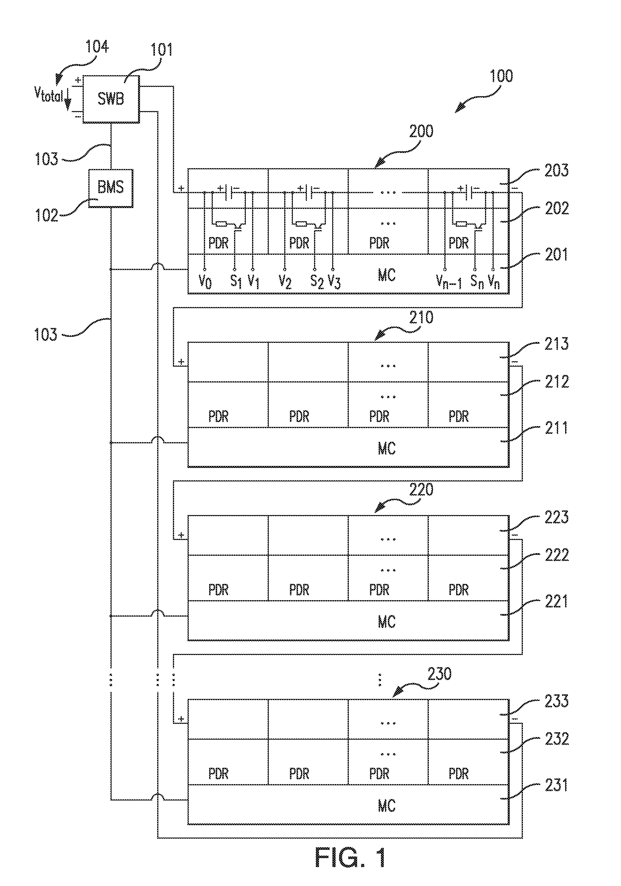
[0039]FIG. 1 shows a schematic view of a multi-cell battery system 100 according to an example embodiment of the present invention.

[0040]In FIG. 1 a number of battery modules 200, 210, 220, 230 containing multi cell-batteries are electrically connected in series. The resulting total voltage of the battery cells thereby adding up to the desired battery systems' total output voltage Vtotal 104, which can be accessed via the output terminals of the switchbox 101. The switchbox 101 indicated with SWB in box 101 is a subsystem of the battery system 100 and includes internal contactors that connect or disconnect the battery system's primary electrical power interfaces to an electrical load. In one example, the electrical load connected to the electrical power interface could be the sum of electrical consumers in an electrical vehicle. For connecting or disconnecting the contactors a relay or power electronic switches with power semiconductors can be used. The configuration of the system a...


PUM


Abstract

A method for balancing voltage for a multi-cell battery system, in which the battery system includes at least two parallel groups of cells connected in series and in which the parallel group of cells includes at least one battery cell, includes: charging the battery system by keeping the voltage of all parallel groups of cells less than or equal to a second threshold voltage value, while at least the voltage of one group of parallel cells is less than or equal to a first threshold voltage; and while at least the voltage of one group of parallel cells is less than or equal to a second threshold voltage; and while the charging current is above a predefined minimal current. The method further includes measuring the voltage of each parallel group of cells while electrical loads are shut off and dissipating energy in each of the parallel group of cells of the amount that is represented by the voltage difference between the individual parallel group of cells and the parallel group of cells with the lowest voltage.

Description

CROSS-REFERENCE TO RELATED APPLICATIONS[0001]The present application claims the benefit of U.S. Provisional Patent Application No. 61 / 420,536, filed on Dec. 7, 2010, which is expressly incorporated herein in its entirety by reference thereto.FIELD OF THE INVENTION[0002]The present invention relates to balancing batteries and more particularly relates to a method of balancing batteries for use in a electric vehicle. The present invention also relates to a cell balancing system and an electric vehicle including a cell balancing system.BACKGROUND INFORMATION[0003]Certain electric vehicles for transportation purposes are conventional. To achieve an acceptable range of transportation for these vehicles they have to be configured to carry and to provide the needed electrical energy to the drive train. Conventional cars have a gasoline tank in which the transportation energy is carried, and that energy is stored in the form of gasoline. The car can not drive any further if the tank is comp...

Claims


Application Information

Patent Timeline
IPC IPC(8): H02J7/04
CPCH02J7/0016Y02T10/7055B60L3/0046B60L3/0069Y02T10/7061B60L2240/545B60L2240/547B60L2240/549Y02T10/7005B60L11/1866B60L58/21B60L58/22Y02T10/70
Inventor EBERHARD, MARTINDIAMOND, STEVETARPENNING, MARCRILEY, JESSICABARKE, ALEXANDERAMMLER, MANFREDHOFMANN, REINHARD
Owner VOLKSWAGEN AG
Why Eureka
Try Eureka