Thermal Deposition Surface Treatment Method, System and Product

a surface treatment and thermal deposition technology, applied in heat treatment furnaces, heat treatment apparatus, furnaces, etc., can solve problems such as thermal degradation, damage to thermal stresses, overheating of coatings and workpieces, etc., to achieve reliable thermal measurement, reduce internal stresses, and excellent production rates

Active Publication Date: 2008-04-17
AIR PROD & CHEM INC
View PDF10 Cites 49 Cited by
  • Summary
  • Abstract
  • Description
  • Claims
  • Application Information

AI Technical Summary

Benefits of technology

[0043] Advantages can be achieved based on using the thermal treatment processes and systems of this invention and may include one or more of the following: an ability to achieve excellent production rates without the risk of overheating and thermally damaging the workpiece material, or underheating and thermally damaging the coating material, or not achieving the desired effect on the substrate material; an ability if coating to produce well adhering, uniform coatings on workpieces while minimizing damaging internal stresses between the coating and the surface in the coated workpiece; an ability to provide temperature control for difficult to control operations optionally involving coolants or heating means, which may also include simplicity of implementation in production environment, reliable thermal measurement in spite of various momentary process upsets, and acceptance of both contact and non-contact sensor measurement; and, an ability to employ mixed inputs from differing temperature sensing devices.

Problems solved by technology

Improper temperature control during thermal deposition frequently, leads to coating and workpiece overheating, thermal degradation, and damaging thermal stresses due to a mismatch of thermal contraction coefficients between the coating and substrate surface.
When damage occurs through overheating, thermal stress and the like, the resulting coatings may be poorly adhering, or even fractured.
Similar problems with non-optimal and / or non-uniform temperature distribution of surface treated components can take place during coating post-treatments, e.g. the conventional flame, laser, plasma, or induction field fusing or glazing of previously spray-deposited coatings in order to close microporosity and densify these deposits.
Cooling air jets are often used to offset the loss of process productivity due to such a practice but (a) air cooling is usually insufficient and (b) the oxygen along with residual moisture and hydrocarbons present in the cooling air often are detrimental to the quality of coating.
While cryogenic cooling methods offer a significant enhancement in the ability to remove heat fast, they are rarely used in the thermal deposition coating industry because of an even further increased difficulty, or a narrower margin for error, in controlling temperature, i.e., heat build-up and thermal uniformity within the workpiece during coating.
Difficult to achieve in the industrial conditions with the conventional approaches, tight control of substrate surface temperature is, nevertheless, critical for maximizing the thickness of coatings and / or adhesion of these coatings to substrate surface.

Method used


Image

  • Thermal Deposition Surface Treatment Method, System and Product
  • Thermal Deposition Surface Treatment Method, System and Product
  • Thermal Deposition Surface Treatment Method, System and Product

Examples


example 1

[0095] The purpose of this example is to more fully explain the control parameters enumerated in the description of the process steps shown in FIG. 6. FIGS. 4, 5 and 6 are used to facilitate the description.

[0096]FIG. 4 illustrates a thermal deposition process employing a workpiece 40 comprised of a workpiece substrate surface 41 which has cylindrical shape and which is rotated during the thermal deposition coating process. The workpiece (RW) comprised of workpiece substrate surface 41 is mounted in a remotely actuated, rotating holder (RWA) 42, and exposed to hot coating deposition material 46 from the thermal deposition head (TCD) 44 which, in turn, traverses over the workpiece surface by the means of a separate actuated holder (TCDA). Traversing in sync with thermal deposition head 44 is an elongated, cryogenic coolant distributor (SCMD) 48 which provides the cooling effect either to the coated only portion of the substrate 41 or to the uncoated and coated portions of the workpi...

example 2

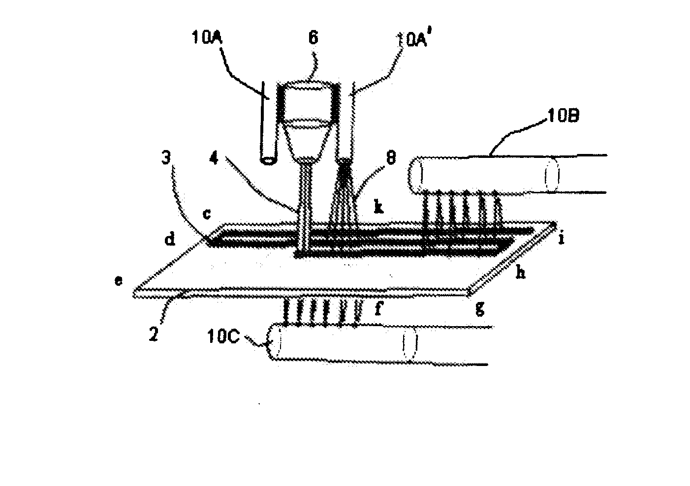
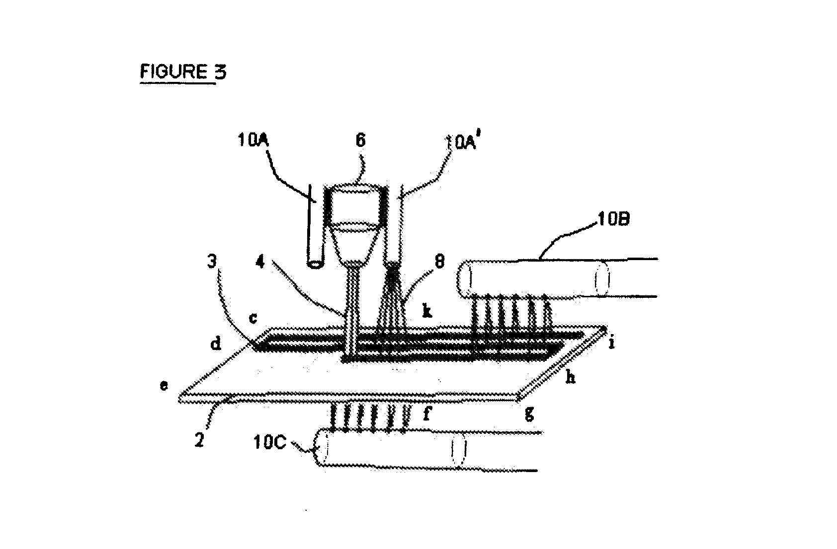
[0105]FIG. 3 is a view of a thermal deposition process employing, optionally, both traversing and stationary cryogenic coolant delivery systems for the workpiece. Common pieces of equipment to those shown in FIG. 1 are similarly numbered. In showing a method for establishing cooling in the thermal deposition coating operations using a cryogenic gas coolant media, one or more coolant means 10A, 10A′, 10B and 10C provide a coolant 8. These coolant means, such as 10A, 10A′ may move with thermal deposition head 4, move as the distributor 48 shown in FIG. 4 moves, or remain stationary. Cooling the top side of the workpiece, that is the surface of the workpiece to be coated, where the heat is deposited with coating material is more desired than cooling the back side of the workpiece because of the resultant stress distribution. Of course, cooling the top side of the workpiece surface, whether the cooled portion of the surface was already coated or not, is more difficult. In one embodiment...

example 3

[0107] Industrial tests of the present system and method were carried out during HVOF spray coating operation involving WC-Co coating material. The HVOF gun was spraying 45 grams of WC-Co powder per minute at an elongated, rotating airplane landing gear component made of high-strength steel. The surface speed of the rotating component was 150 ft / minute, the gun traverse speed along was ⅛-inch per each revolution, the distance between the gun nozzle and the component surface was about 9 inches. The HVOF flame was hydrogen-oxygen, with the hydrogen flowrate of 1525 standard cubic feet per hour at 150 psig supply pressure, and the oxygen flowrate of 475 standard cubic feet per hour at 165 psig supply pressure. Four cryogenic fluid nozzles were more or less uniformly positioned along the axis of the rotating component at the distance of about 4 inches from its surface. The nozzles were discharging a 2-phase mixture of cryogenic nitrogen vapor and fog-size droplet spray toward the surfac...


PUM

PropertyMeasurementUnit
Thicknessaaaaaaaaaa
thicknessesaaaaaaaaaa
temperatureaaaaaaaaaa

Abstract

A process for treating a workpiece, said process comprising the steps of: (c) altering the temperature of a workpiece surface wherein at least one condition selected from the group of: thermal treatment rate, relative motion between the surface and said thermal treatment rate, coolant flow rate onto said surface, heating flow rate onto said surface and the relative speed between the heating means or the cooling means and the surface is controllable; (d) simultaneously measuring temperatures at a plurality of locations over the surface of the workpiece; (c) determining an average temperature of the temperatures measured in step (b); (d) comparing the average temperature to a preselected minimum temperature and a preselected maximum temperature for the workpiece; and (e) automatically adjusting at least one of the controllable conditions if said average temperature is not between the preselected minimum temperature and the preselected maximum temperature for the workpiece. A system for performing a thermal treatment process and the resulting product are also provided. Standard deviations of all temperature readings and controlling the relative motion speed between the thermal coating deposition head and the workpiece provide another improvement for obtaining temperature uniformity over the workpiece surface.

Description

[0001] This application claims priority provisional application 60 / 851,197, filed Oct. 12, 2006, entitled “Thermal Deposition Surface Treatment Method, System and Product”, which is incorporated in its entirety herein by reference.BACKGROUND OF THE INVENTION [0002] Processes for applying various coatings such as metallic, alloy, ceramic and composite to a variety of substrates to form component products using thermal deposition coating methods are known. Such processes are employed to improve properties of the substrate such as hardness, corrosion resistance, heat resistance surface porosity and the like. Exemplary thermal deposition coating operations include: high-velocity oxy-fuel spraying (HVOF) and high-velocity air-fuel spraying (HVAF), DC and RF plasma spray in air atmosphere, vacuum chamber and / or inert gas chamber, electric arc (twin and single wire) spraying, laser powder coating or cladding, transferred arc coating operations such as plasma transferred-arc powder coating ...

Claims


Application Information

Patent Timeline
Patent Type & Authority Applications(United States)
IPC IPC(8): C21D11/00B05D1/02C23C14/28C23C16/00
CPCC23C4/02C23C8/02Y02T50/67C23C24/02C23C10/02Y02P10/25C21D9/00C23C8/00C23C14/58C23C16/56Y02T50/60
Inventor ZURECKI, ZBIGNIEWWARD, CHRISTOPHER ALAN
Owner AIR PROD & CHEM INC
Why Eureka
Try Eureka