Locator with apparent depth indication

a technology of apparent depth and locator, which is applied in the direction of electric/magnetic detection for transportation, instruments, and reradiation, etc., can solve the problems of affecting the comfort and convenience of residents, and affecting the accuracy of locating and tracing. the effect of reliable horizontal field asymmetry measurements, improved user interface integration, and improved accuracy

Active Publication Date: 2006-10-19
SEEK TECH
View PDF4 Cites 48 Cited by
  • Summary
  • Abstract
  • Description
  • Claims
  • Application Information

AI Technical Summary

Benefits of technology

[0016] This invention addresses the above unresolved problems by introducing for the first time a locator with integral event detection in combination with improved measurement of the horizontal magnetic field asymmetry and improved user interface (UI) integration. This invention arises in part from the unexpectedly advantageous observation that two horizontally-spaced one-dimensional sensors disposed proximate to two vertically-spaced three-dimensional sensor arrays operate to produce reliable horizontal field asymmetry measurements without disabling the three-dimensional field vector measurements. Su

Problems solved by technology

If excavation equipment such as a backhoe hits a high voltage line or a gas line, serious injury and property damage may result.
Unintended severing of water mains and sewer lines generally leads to messy and expensive cleanup efforts.
The unintended destruction of power and data cables may seriously disrupt the comfort and convenience of residents and bring huge financial costs to business.
Also, many sites are host to a variety of overhead power and related lines, which emit electromagnetic fields that cannot be readily segregated from the emissions of similar buried lines.
Some transmitters known in the art can produce several different signals at different frequencies for application to the same underground object or even to different underground objects, but a problem with these systems arises when several pipes are located in the same area and the location of all pipes is desired.
Signals transmitted by several pipes can interfere and complicate the detection process.
Modern utility line tracing places complex demands on the locator user, who may b

Method used


Image

  • Locator with apparent depth indication
  • Locator with apparent depth indication
  • Locator with apparent depth indication

Examples


embodiment 62

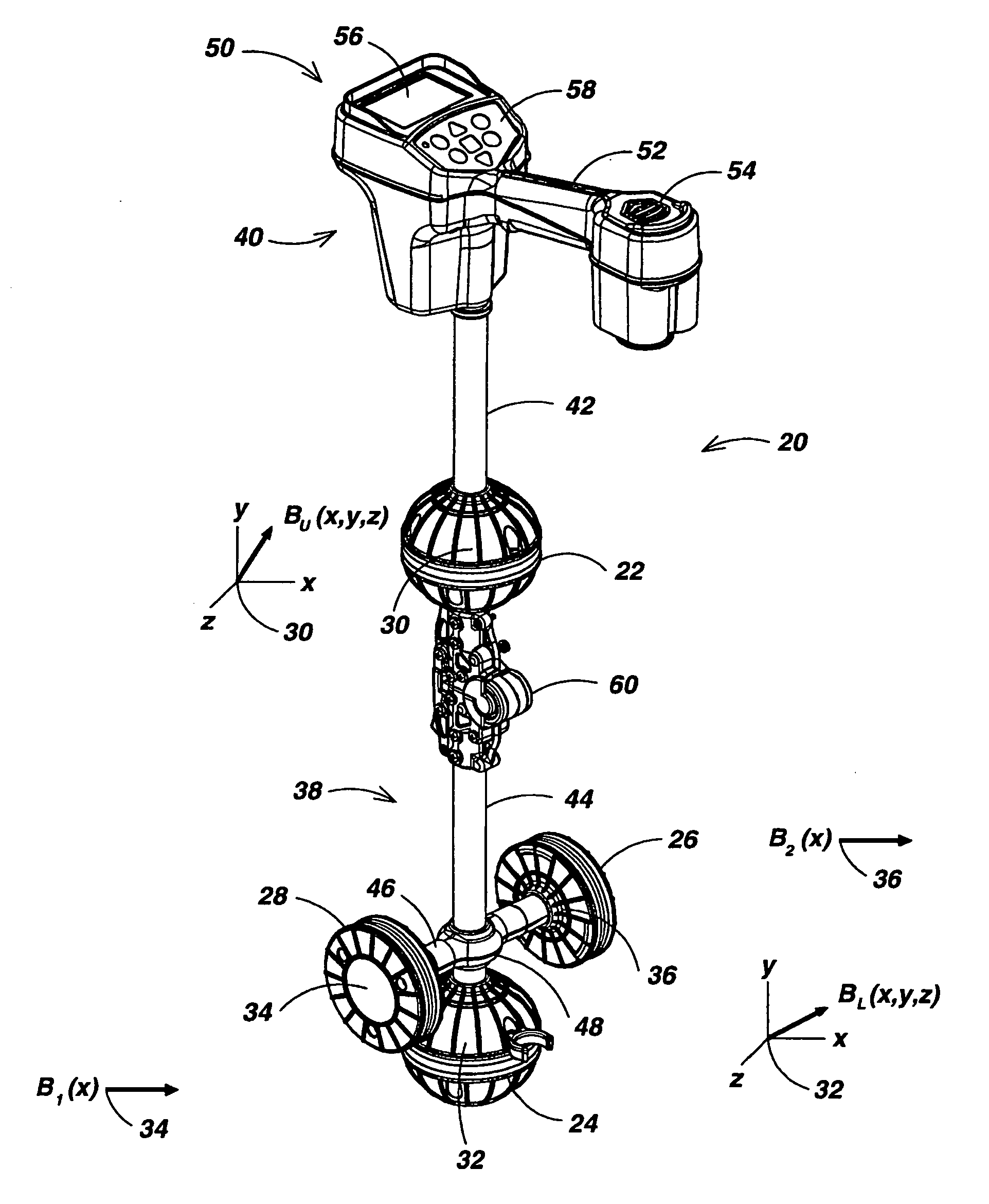
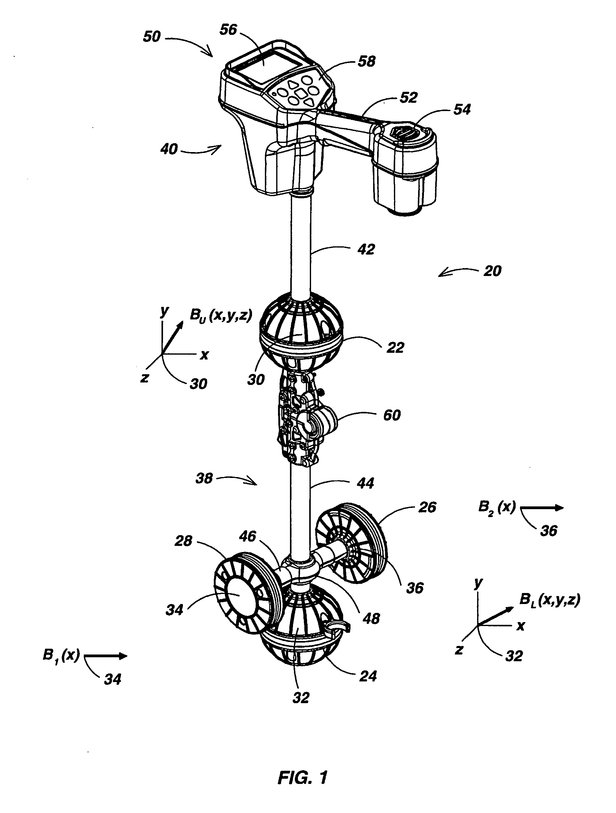
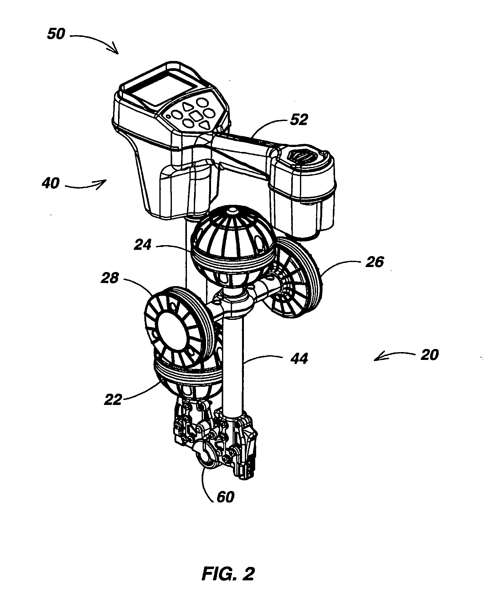
[0043]FIG. 3 is a perspective view illustrating an alternative 3D tripod embodiment 62 ofthe locator system of this invention shown in an operational configuration. Locator system 62 includes a first pair of electromagnetic sensor arrays 64 and 66 that are vertically spaced apart from one another and a second triplet of electromagnetic sensor arrays 68, 70 and 72 that are spaced apart from one another and disposed in a plane below sensor arrays 64 and 66 that may be substantially horizontal during operation. Sensor arrays 64-72 each preferably include three individual sensor elements (not shown) each having a sensor axis disposed in a mutually orthogonal arrangement that facilitates the detection of the 3D electromagnetic field vector BU(x,y,z) at the upper array centroid 74, the 3D electromagnetic field vector BL(x,y,z) at the lower array centroid 76, and the 3D electromagnetic field vectors B1(x,y,z), B2(x,y,z) and B3(x,y,z) at the respective coplanar array centroids 78, 80 and 82...

embodiment 126

[0056] The system of this invention includes several user signal schemes adapted for improved human factors in the communication of events to the user. One of these is a digital “proximity” numeral that is revalued inversely to changes in virtual depth 118. The line 122 in FIG. 8D illustrates exemplary values for the digital proximity numeral, which is illustrated as the proximity numeral display 124 in the exemplary Graphical User Interface (GUI) display embodiment 126 of FIG. 9. Another user signal scheme is the true line current display 125 (FIG. 9), which is presented only when the locator system is disposed directly above the utility line target. Yet another such user signal scheme of this invention is the auditory signal represented by the line 128 in FIG. 8F, which has a frequency that is varies monotonically with the inverse of virtual depth 118 above some predetermined threshold and is otherwise not present. An important feature of the signal frequency represented by line 1...


PUM


Abstract

A human-portable utility locator system for locating and tracing a buried utility line characterized by an electromagnetic field emission. The locator may include a horizontal spaced sensor pair for detecting the horizontal field asymmetry of the emitted field in one or more independent frequency bands, which is employed to assist in determining an accurate “virtual depth” measurement for producing detection events. An event detector may be disposed to detect events corresponding to extremum in the B-field gradient with respect to time and a user interface (UI) coupled to the event detector signals the detected event to a user. In a preferred embodiment, one pair of spaced-apart 3D magnetic sensor arrays is disposed substantially orthogonal to another intermediate spaced-apart pair of sensors.

Description

CROSS-REFERENCES TO RELATED APPLICATIONS [0001] This application is related by common inventorship and subject matter to the commonly-assigned patent application Ser. No. 10 / 268,641, published on Apr. 15, 2004 as U.S. Patent Application No. 2004 / 0070399 A1, which is entirely incorporated herein by this reference. This application is also related by common inventorship and subject matter to the commonly-assigned patent application Ser. No. 10 / 308,752, published on Apr. 15, 2004 as U.S. Patent Application No. 2004 / 0070525 A1, which is entirely incorporated herein by this reference. This application is also related by common inventorship and subject matter to the commonly-assigned patent application Ser. No. 10 / 956,328 filed on Oct. 01, 2004, and patent application Ser. No. 11 / 054,776 filed on Feb. 9, 2005, which are both entirely incorporated herein by this reference.BACKGROUND OF THE INVENTION [0002] 1. Field of the Invention [0003] This invention relates generally to systems for loc...

Claims


Application Information

Patent Timeline
IPC IPC(8): G01R19/00
CPCG01R29/0871G01V3/15G01R29/0878
Inventor OLSSON, MARK S.MARTIN, MICHAEL J.MAIER, CHRISTOPH H.STUART, PAUL G.
Owner SEEK TECH
Why Eureka
Try Eureka