Sheet conveying apparatus and image forming apparatus

a conveying apparatus and a technology of forming apparatus, applied in the direction of applications, roads, roads, etc., can solve the problems of increased manufacturing cost of the roller (insulating roller), and low hardness of the insulator layer of the insulator, so as to achieve the effect of reliably conveying a sheet with a low cost and without deterioration of image quality

Active Publication Date: 2011-10-25
CANON KK
View PDF13 Cites 2 Cited by
  • Summary
  • Abstract
  • Description
  • Claims
  • Application Information

AI Technical Summary

Benefits of technology

[0014]The present invention provides a sheet conveying apparatus capable of reliably conveying a sheet with a low cost, without deteriorating image quality and an image forming apparatus including the same.
[0017]According to the above aspects of the invention, it is possible to reliably convey a sheet with a low cost, without deteriorating image quality.

Problems solved by technology

Consequently, the color of the toner image is changed, or a so-called roller trace, which is viewed as a brilliance difference, occurs, which results in deterioration of image quality.
However, in the sheet conveying apparatus according to the related art that uses the roller having an insulating property, the manufacturing cost of the roller (insulating roller) is increased since a material forming the insulator layer is expensive.
In addition, the hardness of an insulator forming the insulator layer is low.
As a result, a roller trace occurs, and image quality deteriorates.
As a result, it is difficult to reliably discharge sheets.
When the toner parting property deteriorates as described above, the following problem arises.
When the sheet having the toner image heated and fixed thereto passes through a pair of rollers before the toner image is cooled down, toner on the sheet is peeled off, which results in deterioration of image quality.
When a contact area between toner and the rollers is small and the heights of contact portions between the minute protrusions and the sheet are not uniform, the minute protrusions formed on the outer circumferential surface of the roller cause high pressure to be locally applied to the sheet.
Consequently, toner on the sheet is peeled off, or the sheet is deformed and an uneven portion is formed on the sheet.
As a result, image quality deteriorates.
As a result, a contact area between toner on the sheet and the roller is increased, and it is difficult to sufficiently prevent the generation of a roller trace.

Method used


Image

  • Sheet conveying apparatus and image forming apparatus
  • Sheet conveying apparatus and image forming apparatus
  • Sheet conveying apparatus and image forming apparatus

Examples


first embodiment

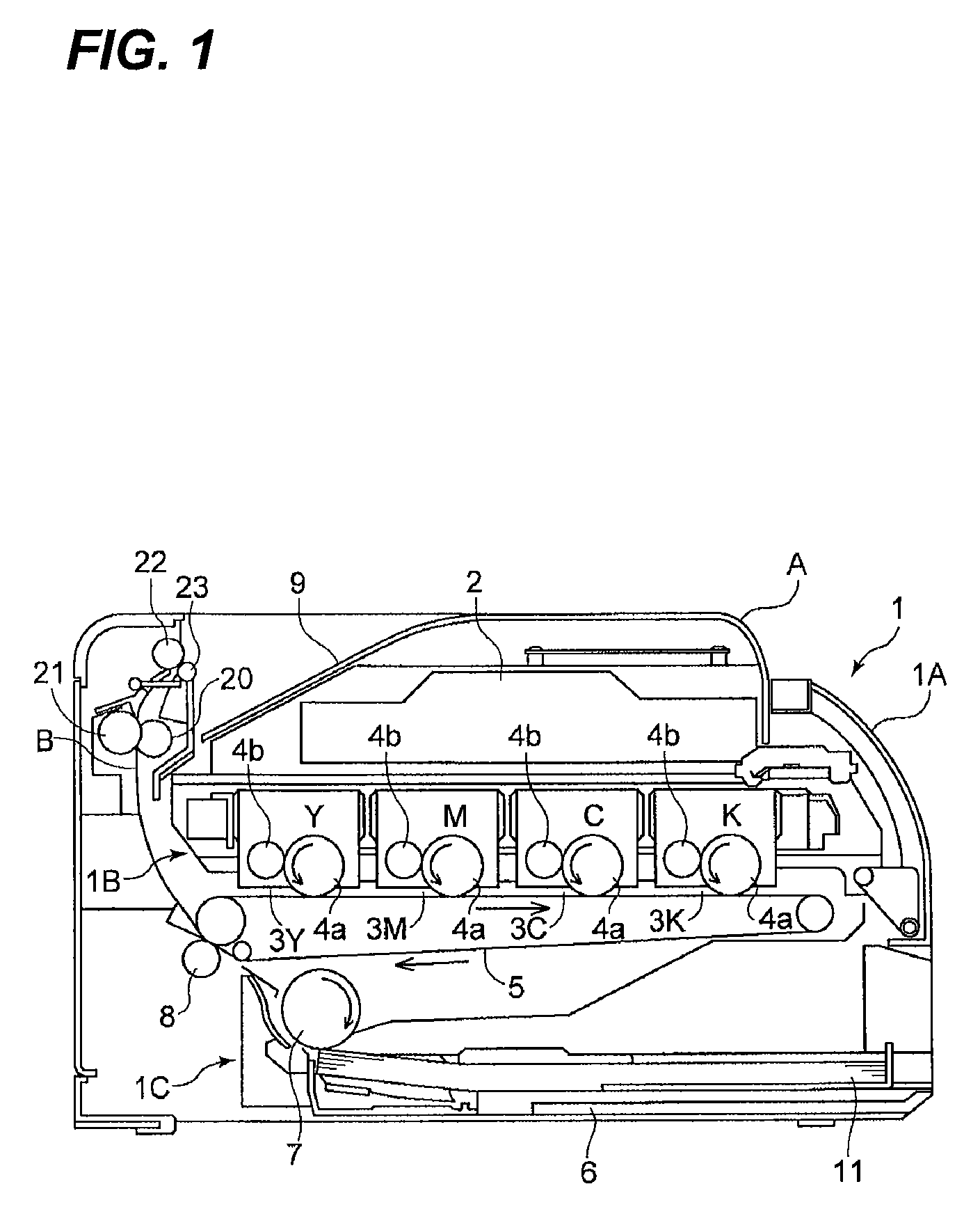
[0030]FIG. 1 is a diagram illustrating the structure of a laser beam printer, which is an example of an image forming apparatus according to the invention. In FIG. 1, a laser beam printer 1 includes a laser beam printer body 1A (hereinafter, referred to as a printer body).

[0031]A laser scanner 2 is provided above the printer body 1A, and an image forming portion 1B is provided below the laser scanner 2. In this embodiment, the image forming portion 1B forms an image using electrophotographic system, and includes four image forming units 3 (3Y, 3M, 3C, and 3K) that form yellow (Y), magenta (M), cyan (C), and black (K) toner images, respectively.

[0032]The image forming units 3 have the same structure except for toner colors. In each of the image forming units, a charging unit (not illustrated) uniformly charges a photosensitive drum 4a and the laser scanner 2 radiates light corresponding to an image signal to the photosensitive drum, thereby forming an electrostatic latent image. Then...

second embodiment

[0077]Next, the invention will be described.

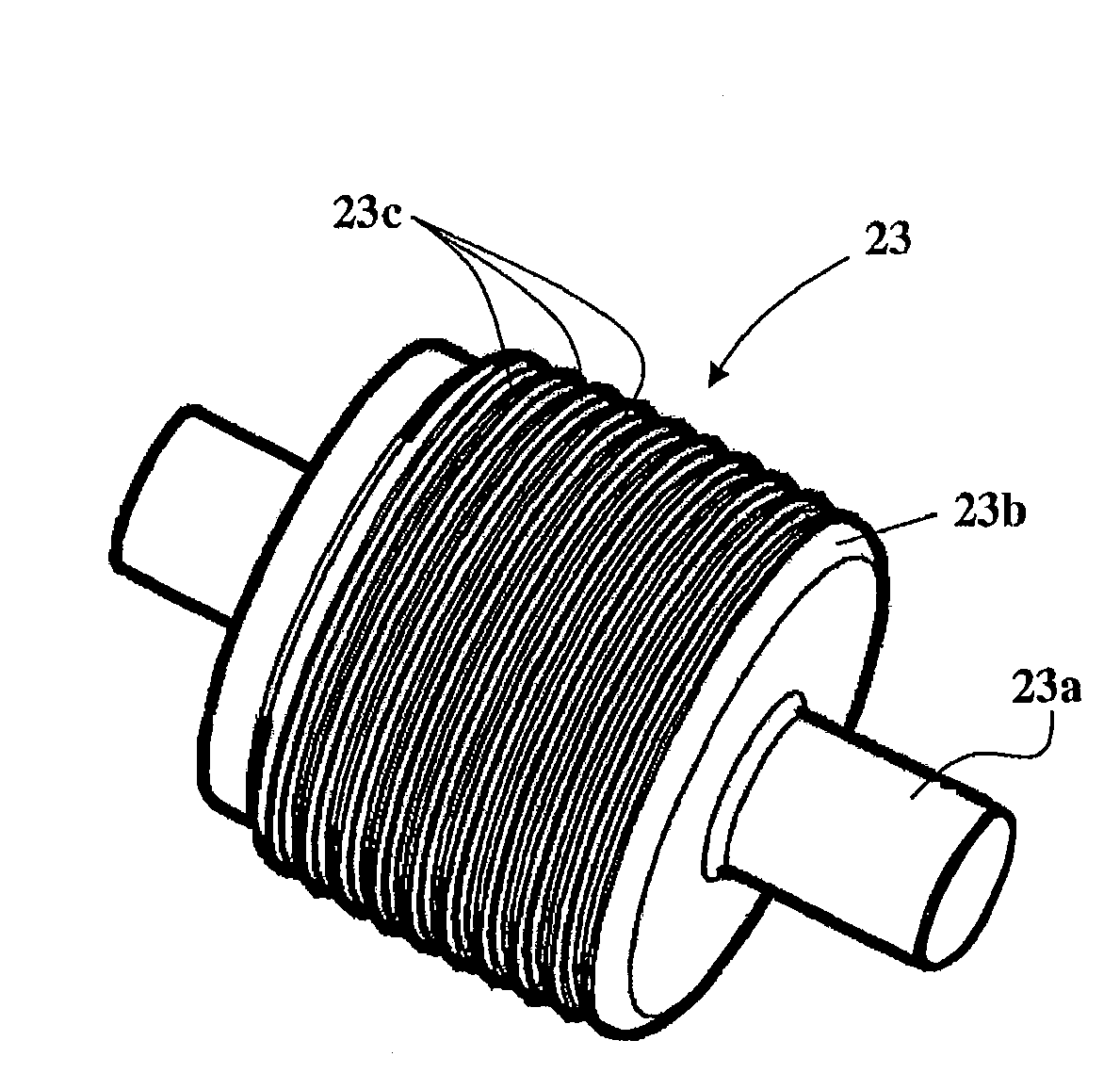
[0078]FIG. 9 is a diagram illustrating a discharge skid provided in a sheet conveying apparatus according to the second embodiment. In FIG. 9, the same components or equivalents as those illustrated in FIG. 5 are denoted by the same reference numerals.

[0079]In this embodiment, as illustrated in FIG. 9, 10 minute ribs 23c are provided. Six minute ribs 23c disposed at the center of the discharge skid 23 have the same outside diameter, and the outside diameters of four minute ribs 23c disposed at both ends of the discharge skid in the axial direction are gradually reduced toward both ends.

[0080]In the above-mentioned structure, the height differences ΔH1 and ΔH2 between adjacent minute ribs 23c disposed at the center of the discharge skid 23 is approximately 0 μm. It is preferable that the height differences ΔH1 and ΔH2 is 20 μm or less in order to prevent deterioration of image quality. When the height differences ΔH1 and ΔH2 are 20 μm or le...


PUM

PropertyMeasurementUnit
widthaaaaaaaaaa
widthaaaaaaaaaa
widthaaaaaaaaaa

Abstract

A sheet conveying apparatus for conveying a sheet having an image formed thereon includes: a first rotator; a second rotator that comes into pressure contact with the first rotator and contacts a surface of the sheet having the image formed thereon; and a plurality of ribs that are formed on a circumferential surface of the second rotator and disposed in an axial direction so as to be continuous in a circumferential direction. Among the plurality of ribs, the ribs disposed at both ends of the second rotator in the axial direction have a diameter that is smaller than those of the other ribs.

Description

BACKGROUND OF THE INVENTION[0001]1. Field of the Invention[0002]The present invention relates to a sheet conveying apparatus and an image forming apparatus.[0003]2. Description of Related Art[0004]In image forming apparatuses according to the related art, such as a copying machine, a printer, and a facsimile, a toner image formed on a photosensitive drum, which is an image bearing member, provided in an image forming portion is transferred onto a sheet, and the sheet is conveyed to a fixing device. Then, the fixing device heats and presses the sheet to fix the toner image to the sheet, and a sheet conveying apparatus discharges the sheet having the toner image fixed thereto to a sheet discharging and stacking portion.[0005]However, in the image forming apparatus according to the related art, for example, when a roller comes into contact with a surface of the sheet having the toner image formed thereon or the rear surface thereof before the toner image that is heated and fixed at a h...

Claims


Application Information

Patent Timeline
Patent Type & Authority Patents(United States)
IPC IPC(8): B65H29/70
CPCB65H29/14B65H2301/5122B65H2404/133B65H2404/14B65H2404/513B65H2801/06
Inventor SUZUKI, TETSUJI
Owner CANON KK
Why Eureka
Try Eureka