Sheet conveying apparatus and image forming apparatus
a conveying apparatus and a technology of forming apparatus, applied in the direction of applications, roads, roads, etc., can solve the problems of increased manufacturing cost of the roller (insulating roller), and low hardness of the insulator layer of the insulator, so as to achieve the effect of reliably conveying a sheet with a low cost and without deterioration of image quality
- Summary
- Abstract
- Description
- Claims
- Application Information
AI Technical Summary
Benefits of technology
Problems solved by technology
Method used
Image
Examples
first embodiment
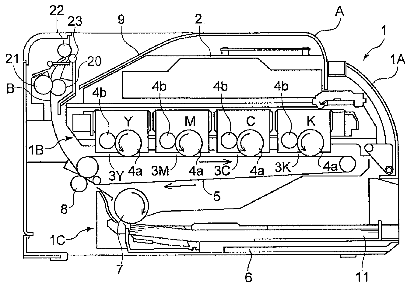
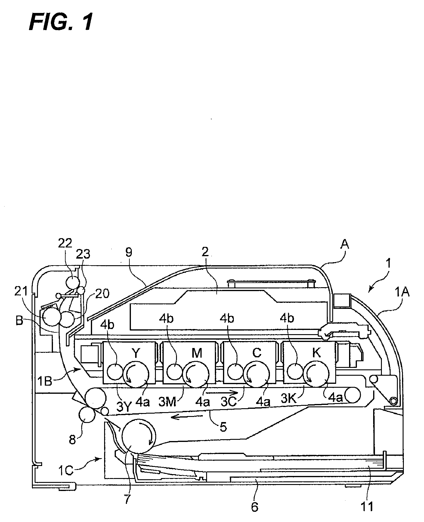
[0030]FIG. 1 is a diagram illustrating the structure of a laser beam printer, which is an example of an image forming apparatus according to the invention. In FIG. 1, a laser beam printer 1 includes a laser beam printer body 1A (hereinafter, referred to as a printer body).
[0031]A laser scanner 2 is provided above the printer body 1A, and an image forming portion 1B is provided below the laser scanner 2. In this embodiment, the image forming portion 1B forms an image using electrophotographic system, and includes four image forming units 3 (3Y, 3M, 3C, and 3K) that form yellow (Y), magenta (M), cyan (C), and black (K) toner images, respectively.
[0032]The image forming units 3 have the same structure except for toner colors. In each of the image forming units, a charging unit (not illustrated) uniformly charges a photosensitive drum 4a and the laser scanner 2 radiates light corresponding to an image signal to the photosensitive drum, thereby forming an electrostatic latent image. Then...
second embodiment
[0077]Next, the invention will be described.
[0078]FIG. 9 is a diagram illustrating a discharge skid provided in a sheet conveying apparatus according to the second embodiment. In FIG. 9, the same components or equivalents as those illustrated in FIG. 5 are denoted by the same reference numerals.
[0079]In this embodiment, as illustrated in FIG. 9, 10 minute ribs 23c are provided. Six minute ribs 23c disposed at the center of the discharge skid 23 have the same outside diameter, and the outside diameters of four minute ribs 23c disposed at both ends of the discharge skid in the axial direction are gradually reduced toward both ends.
[0080]In the above-mentioned structure, the height differences ΔH1 and ΔH2 between adjacent minute ribs 23c disposed at the center of the discharge skid 23 is approximately 0 μm. It is preferable that the height differences ΔH1 and ΔH2 is 20 μm or less in order to prevent deterioration of image quality. When the height differences ΔH1 and ΔH2 are 20 μm or le...
PUM
| Property | Measurement | Unit |
|---|---|---|
| contact width | aaaaa | aaaaa |
| contact width | aaaaa | aaaaa |
| contact width | aaaaa | aaaaa |
Abstract
Description
Claims
Application Information
 - R&D
- Intellectual Property
- Life Sciences
- Materials
- Tech Scout
- Unparalleled Data Quality
- Higher Quality Content
- 60% Fewer Hallucinations
Browse by: Latest US Patents, China's latest patents, Technical Efficacy Thesaurus, Application Domain, Technology Topic, Popular Technical Reports.
© 2025 PatSnap. All rights reserved.Legal|Privacy policy|Modern Slavery Act Transparency Statement|Sitemap|About US| Contact US: help@patsnap.com


