Conveying system

a conveyor chain and conveyor section technology, applied in the direction of conveyors, conveyor parts, transportation and packaging, etc., can solve the problems of high space requirements for conveying installations, and high acquisition, operation and maintenance costs, so as to reduce the load peak acting on the conveyor chain and/or the section, the effect of reducing the peak of the load

Inactive Publication Date: 2018-11-15
WRH WALTER REIST HLDG
View PDF2 Cites 2 Cited by
  • Summary
  • Abstract
  • Description
  • Claims
  • Application Information

AI Technical Summary

Benefits of technology

[0017]With such an embodiment of a conveying system according to the invention, even relatively large and / or heavy piece goods, in particular, can on the one hand be conveyed on the assembled conveying support. On the other hand, however, bulk goods for example, such as for example small or mass-produced parts, loose or for example packaged in small bags, can also be reliably conveyed on the tray. For a large number of applications, it is thus possible to convey or process a wide variety of different goods with the same conveying system.
[0092]According to a further embodiment of the method, it is determined, before the loading of a first and / or a second conveying means, in particular an assembled conveying support and / or a tray, whether such loading would not lead to a critical mechanical loading of the conveying system. For this purpose, it can for example be ascertained how the sections of the conveying system adjacent to a first or second conveying means (respectively the assembled conveying support or the tray) are already loaded with items to be conveyed. Such a determination can take place for example by means of a mechanical device for the weight measurement of the items to be conveyed and / or the measurement of the deformation of a conveyor rail and / or of a tray and / or of a support element. Alternatively or in addition, optical sensors can also be used for this purpose. In this way, damage to the conveying device due to mechanical overload caused by items to be conveyed not being distributed uniformly can be prevented.

Problems solved by technology

On the one hand, this leads to a greater space requirement for the conveying installations, but on the other hand also to relatively high acquisition, operational and maintenance costs.
In addition, if the items conveyed using the different systems have to be brought together—for example in the context of order-picking, an additional installation is required for this purpose or the items have to be brought together manually, which is often also bound up with additional costs.

Method used


Image

  • Conveying system
  • Conveying system
  • Conveying system

Examples


Embodiment Construction

[0106]Corresponding parts are provided with identical reference numbers, unless indicated otherwise, in the following figures and the associated description.

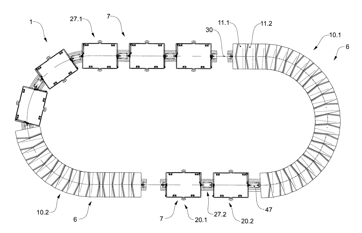
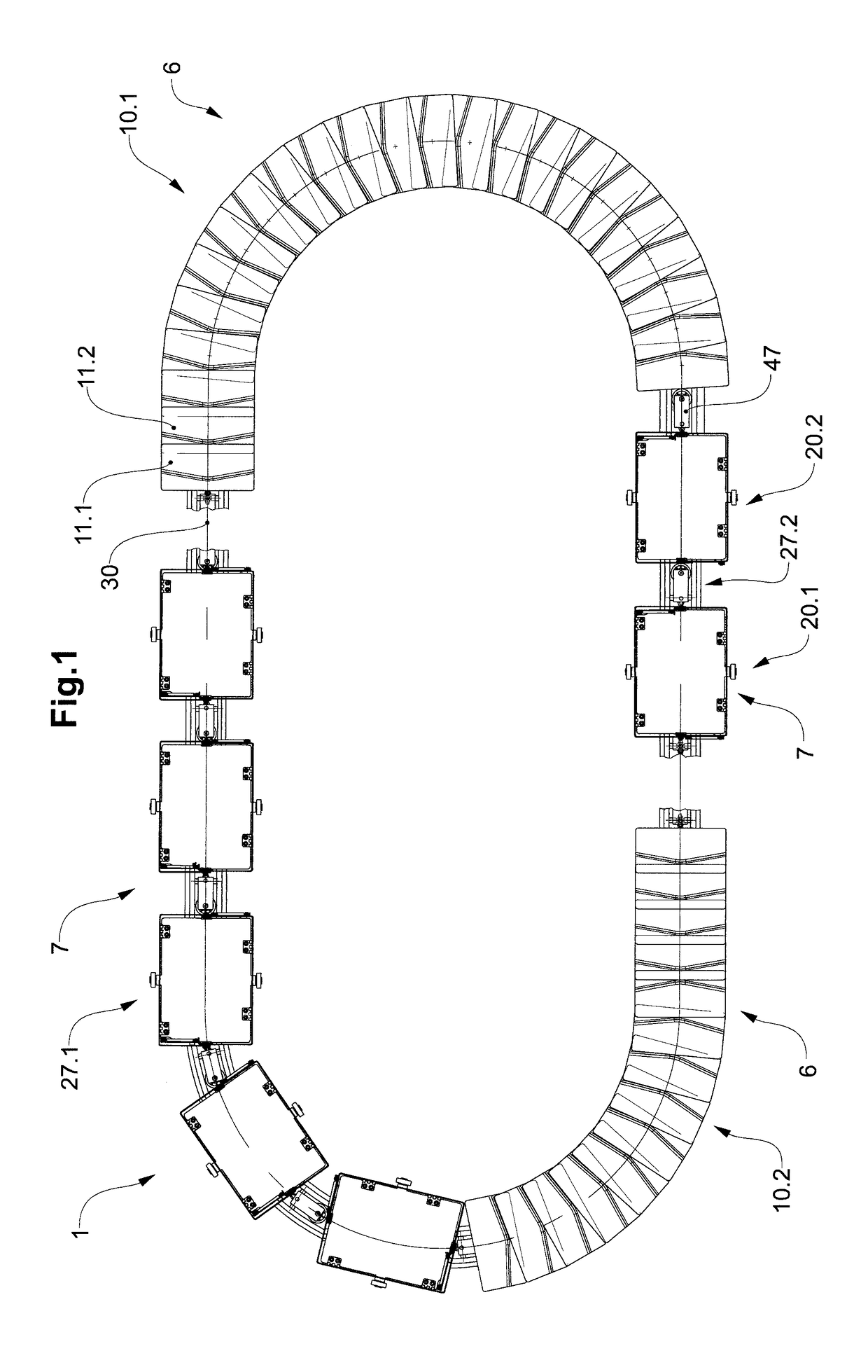
[0107]FIG. 1 shows diagrammatically an embodiment of a conveying system 1 according to the invention comprising two assembled conveying supports 10.1, 10.2, which can be moved along a conveying path 30 and which represent first conveying means 6. For the purpose of better illustration, conveying path 30 is represented interrupted. Assembled conveying supports 10.1, 10.2 are each composed of a number of successive support elements 11.1, 11.2. In the embodiment shown, the two conveying supports 10.1, 10.2 are constituted differently (not represented). A first conveying support10.1 can be formed for example from a highly heat-resistant material, so that relatively hot items to be conveyed can be conveyed with it. Second conveying support 10.2, on the other hand, can comprise for example a surface made a plastic material with a high...


PUM


Abstract

The invention relates to a conveying system (1) for conveying items (2.1, 2.2) to be conveyed. The conveying system (1) comprises a conveying path (30) and at least one first conveying means (6) that can move along the conveying path (30) and is designed to convey a first item (2.1) to be conveyed. The conveying system (1) also comprises at least one second conveying means (7) which can move along the conveying path (30) along with the first conveying means (6) and which is designed to convey a second item (2.2) to be conveyed that is of a different type than the first item (2.1).

Description

BACKGROUND OF THE INVENTIONField of the Invention[0001]The invention lies in the field of conveying technology and relates to a conveying system for conveying items to be conveyed. Furthermore, the invention relates to a method for conveying and delivering items to be conveyed with such a conveying system.[0002]Different conveying systems are known for conveying freely supported items to be conveyed.Discussion of Related Art[0003]WO 2016 / 119071 A1 was filed on 22 Jan. 2016 in the name of WRH Walter Reist Holding AG and shows a conveying unit for a conveying installation in the manner of a tilt-tray conveyor. The shown conveying unit comprises a base body and a support element, which forms a support surface. By means of an inclining mechanism, the support surface can be inclined with respect to the base body, as a result of which an item to be conveyed arranged on the support surface can be delivered to a delivery side. The support surface is enclosed at least partially by a surround...

Claims


Application Information

Patent Timeline
Patent Type & Authority Applications(United States)
IPC IPC(8): B65G17/06B65G47/96
CPCB65G17/065B65G47/962
Inventor MAEDER, CARL CONRAD
Owner WRH WALTER REIST HLDG
Why Eureka
Try Eureka