Device ad method for loading a liquid with a gas

a technology of liquid loading and device ad, which is applied in the direction of transportation and packaging, rotary stirring mixer, other domestic articles, etc., to achieve the effect of convenient adjustmen

Active Publication Date: 2019-07-09
HENKEL KGAA
View PDF9 Cites 3 Cited by
  • Summary
  • Abstract
  • Description
  • Claims
  • Application Information

AI Technical Summary

Benefits of technology

[0007]An object of the invention is to provide a device and a method of the kind specified above having a compact design and enabling the loading of liquids with gasses until saturation in a reliable and, compared with the state of the art, fast manner, without any bubbles of undissolved gas being formed in the liquid.
[0009]When carrying out the method according to the invention with the device according to the invention, the liquid received by the pressure vessel can be agitated by means of the agitator and conveyed inside the vessel through the conveying pipe to a level above the liquid level and conveyed through at least one outlet onto the running-off surface, on which it discharges in a thin layer and at the same time is loaded with the pressurised gas located above the liquid level, wherein, at the same time, undissolved gas contained in the liquid in the form of bubbles is released into the gas atmosphere. The fact that the drive shaft of the agitator also drives the conveying organ, which pumps the liquid in the conveying pipe inside the pressure vessel upwards over the running-off surface, results in a particularly compact design that requires little maintenance due to one single drive being used for both the agitator and the conveying pump. While the agitator ensures an even dispersion of the gas in the liquid, it is also ensured that there is a large exchange area between the gas and the liquid, resulting in the possibility for the gas to be intermixed with and dissolved in the liquid after remaining in the vessel for only a short period of time. This is achieved, in a simultaneous manner to the liquid being agitated by the agitator, by means of the liquid being conveyed to the running-off surface, on which it can discharge in a thin layer and thus come into contact with the pressured air located above the liquid level.
[0010]The conveying organ is preferably formed by a screw conveyor arranged in the conveying pipe being coupled in a torque-proof way to the drive shaft, wherein it has proven advantageous for the screw conveyor to slightly protrude from the conveying pipe at the lower end thereof. This ensures that, even when using highly-viscous, in other words, thick materials, no stall occurs when sucking or pumping them into the conveying pipe. The protrusion of the screw conveyor from the conveying pipe ensures good suction performance and thus reliable conveying of the liquid even with highly-viscous liquids. Equivalent to this solution is an embodiment in which the pipe wall has indentations at the lower end of the conveying pipe distributed over the periphery, through which the viscous material to be conveyed can flow into the screw conveyor.
[0014]A liquid discharge line is expediently connected to the pressure vessel below the liquid level. The liquid discharge line can then be connected to a recirculation line, the other end of which is connected to a liquid inlet into the vessel. The liquid saturated with gas can be discharged out of the pressure vessel for further processing through the discharge line and / or optionally flow back into the vessel through the recirculation line. It is particularly advantageous if a gas load measuring device is attached below the liquid level or the liquid discharge line, using which the level of saturation of the gas in the liquid can be determined. Using said measuring device also enables the device to be easily adjusted to a determined air loading value, by recirculating the material discharged through the discharge line into the vessel until the value detected by the gas load measuring device corresponds to a previously determined desired value, for example a saturation value at a determined processing pressure. Possible parameters for adjustment can be, for example, the initial pressure in the pressure vessel, the amount of additional air blown in and / or the timing or speed of the agitator and therefore also the volume of the amount of liquid conveyed by the screw conveyor.
[0015]In another preferred embodiment of the invention, at least one overflow opening is arranged in the running-off surface, through which the air and / or the liquid can flow upwardly from below. The overflow opening can be blocked against downward flows from above by means of a valve member, preferably an elastic valve plate. By means of said overflow opening, an otherwise large displacement when immersing the mechanism in the vessel and the subsequent rising of the liquid level can be avoided. Having at least one overflow opening ensures that no gas bubble is allowed to form underneath the running-off surface, which otherwise would complicate taking a correct measurement of the filling level, which is required, for example, for refilling the pressure vessel in a controlled manner.

Problems solved by technology

Apart from the fact that the known devices, in particular those with an external recirculation pump, are very complex, the processing times when gassing with such known devices is comparably long and, moreover, it is quite possible for larger bubbles to form in the liquid, resulting in a partially two-phase material, which can cause problems in the subsequent further processing.

Method used


Image

  • Device ad method for loading a liquid with a gas
  • Device ad method for loading a liquid with a gas

Examples


Embodiment Construction

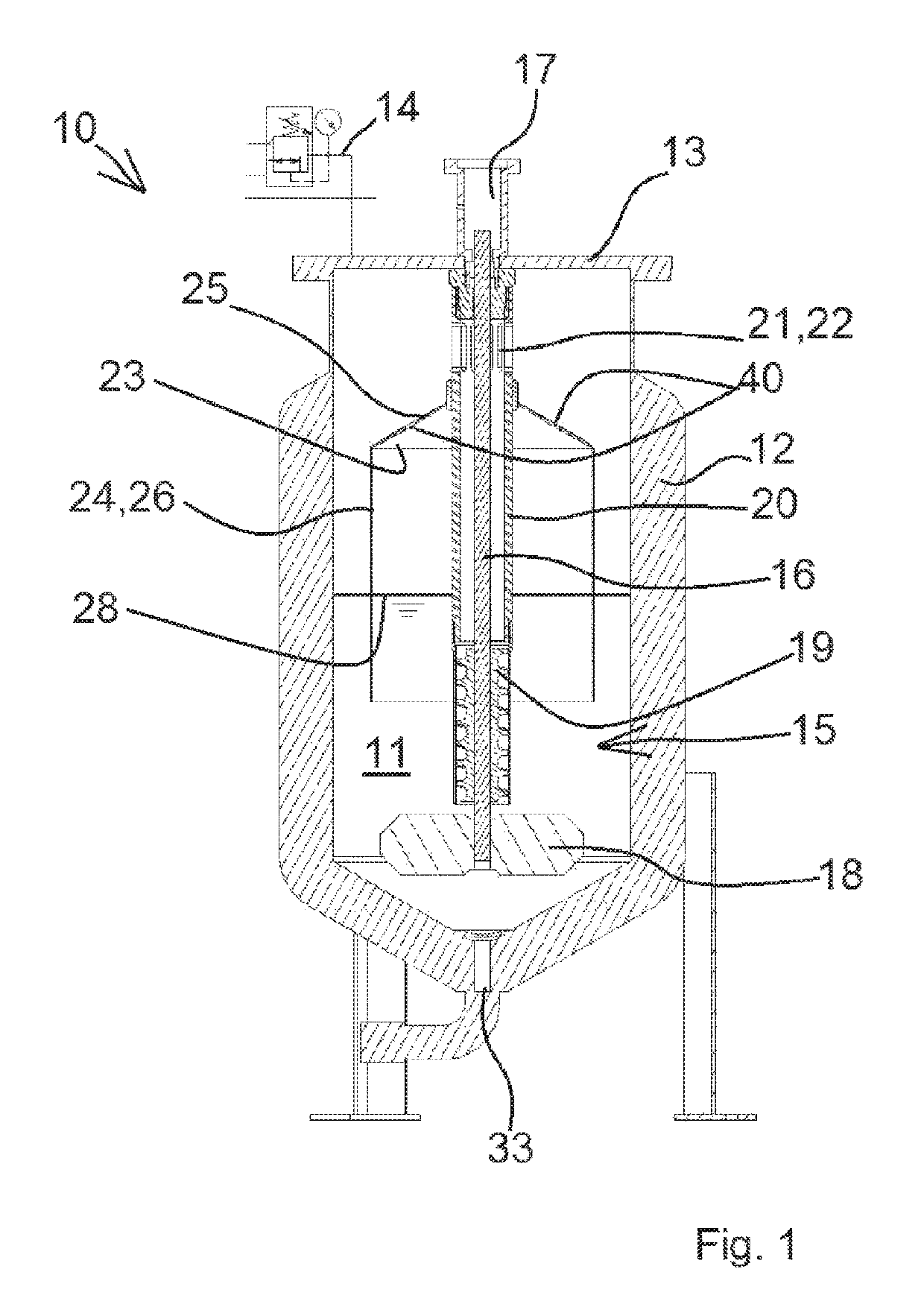
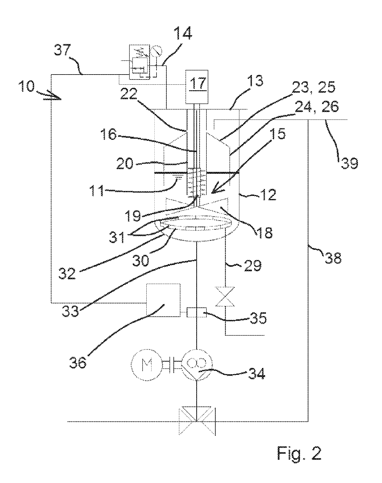
[0022]Referring now to the drawings wherein the showings are for the purpose of illustrating preferred and alternative embodiments of the invention only and not for the purpose of limiting the same, reference sign 10 designates a device in its entirety used to load a higher-viscosity liquid 11, for example a silicone material used to produce a foam gasket, with air under superatmospheric pressure. When using such sealing material, the loading with air has a considerable effect on the subsequent quality of the foam gasket, in particular its surfaces and their pore structure. In general terms, it is intended to load the liquid, in other words the raw sealing material, with air until reaching the saturation limit, without any free air bubbles being present in the liquid. The device 10 according to the invention achieves fast and even dissolution of the air in the liquid, resulting in excellent foam quality when processing the material further at a later stage.

[0023]The device 10 has a ...


PUM

PropertyMeasurementUnit
viscosityaaaaaaaaaa
torqueaaaaaaaaaa
angle of inclinationaaaaaaaaaa

Abstract

A device for loading an in particular higher-viscosity liquid, such as a silicon resin, for example, with air or another gas. The device has a pressure vessel receiving the liquid and the gas, in which pressure vessel an agitator, having a drive shaft set through the pressure vessel at least in part, is arranged. In order to enable the particularly fast and homogeneous intermixing of the liquid and gas, the drive shaft is arranged in a conveying pipe and drives a conveying organ, in particular a screw conveyor, which transports the liquid through the conveying pipe to at least one outlet, and there is an running-off surface underneath the outlet from the conveying pipe for the liquid flowing out of the outlet. Upon actuation of the agitator, the liquid is thus not only well intermixed together with the air already received therein, but at the same time conveyed through the conveying pipe to the running-off surface, on which it can discharge in a thin layer and has a particularly large exchange area with the gas as a result.

Description

[0001]The invention relates to a device for loading an in particular higher-viscosity liquid with a gas, in particular with air, wherein the device has a pressure vessel receiving the liquid and the gas and wherein an agitator having a drive shaft vertically passing through the pressure vessel at least in part is arranged in the pressure vessel. The invention further relates to a method for loading an in particular higher-viscosity liquid with a gas using a device according to the invention.BACKGROUND OF THE INVENTION[0002]When higher-viscosity liquids such as polyurethane or silicone raw materials are used to produce gaskets or the like, the pre-treatment of said viscous materials is of great importance for the quality of the product produced thereafter. The raw materials used are often one or two components of a multi-component system, which are thoroughly mixed in a mixer and then chemically react with each other to produce a gas, usually carbon dioxide, and then, after being eje...

Claims


Application Information

Patent Timeline
Patent Type & Authority Patents(United States)
IPC IPC(8): B01F3/00B29B7/16B01F3/04B01F7/00B01F15/00B01F15/02B29B7/14B01F23/00B29K83/00B29K105/04B29L31/26
CPCB01F3/04992B01F3/04453B01F3/04531B01F3/04744B01F7/00708B01F15/00129B29B7/14B29B7/16B01F15/0251B29L2031/265B01F2003/04673B01F2215/0049B29K2083/00B29K2105/04B01F23/233B01F23/23362B01F23/23411B01F27/2123B01F23/20B01F27/00B01F23/291B01F23/2351B01F35/211B01F35/71775B01F2101/2805
Inventor METZLER, MARIOBALDAUF, GUNTER
Owner HENKEL KGAA
Why Eureka
Try Eureka