Combustion chamber for a gas turbine

a combustion chamber and gas turbine technology, applied in the direction of machines/engines, mechanical equipment, lighting and heating apparatus, etc., can solve the problems of affecting the design of compact turbines and affecting the efficiency of gas turbines, and achieve the effect of compact design

Active Publication Date: 2010-03-11
SIEMENS ENERGY GLOBAL GMBH & CO KG
View PDF2 Cites 86 Cited by
  • Summary
  • Abstract
  • Description
  • Claims
  • Application Information

AI Technical Summary

Benefits of technology

[0023]The invention is directed also at a gas turbine having a combustion chamber as described above. Through combining recirculating on the one hand and, on the other, direct injecting of waste gas from the first jet carrier's flame zone into the second jet carrier's mixing zone, a recirculating space can be kept small and the combustion chamber can be of compact design, which is particularly advantageously applied to a gas turbine.

Problems solved by technology

A consequently necessary large combustion-space cross-section will impede designing a compact turbine.
A large combustion-space cross-section can furthermore cause the gases to have a lengthy dwell time within the combustion space, which will promote the undesired development of nitrogen oxide.

Method used


Image

  • Combustion chamber for a gas turbine
  • Combustion chamber for a gas turbine
  • Combustion chamber for a gas turbine

Examples


Embodiment Construction

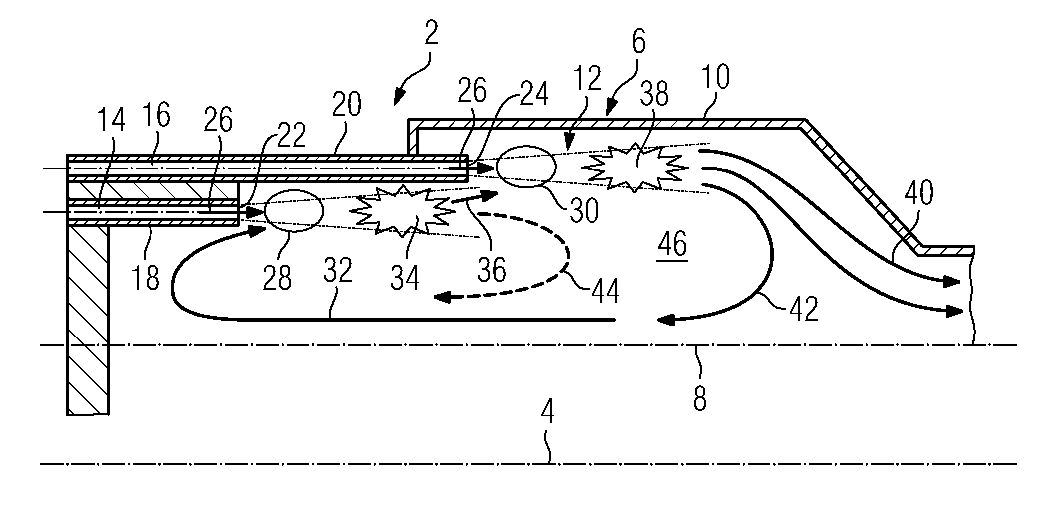
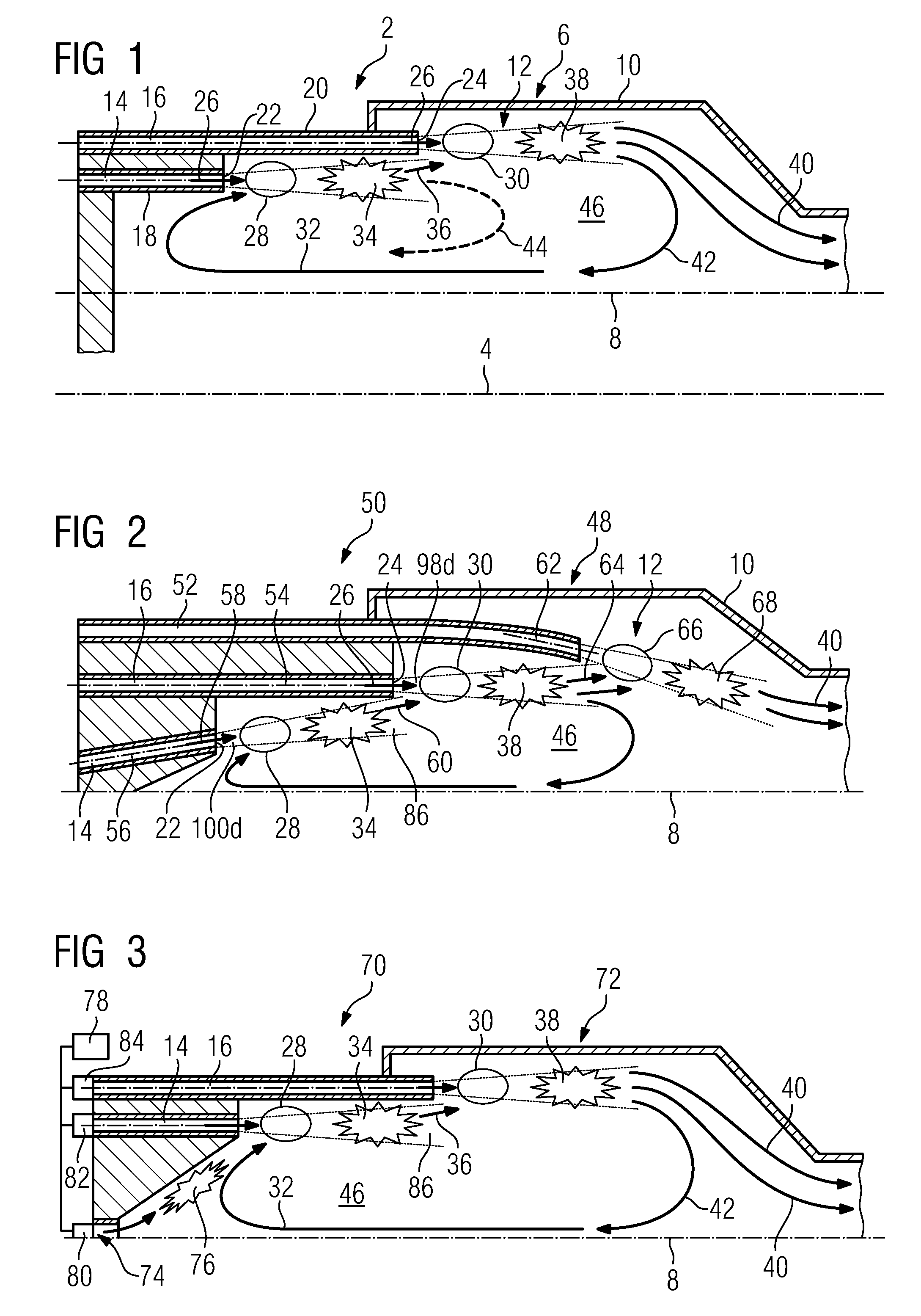
[0029]FIG. 1 shows in a longitudinal section a part of a gas turbine 2 having a shaft that is arranged along a shaft axis 4, though not shown, and a combustion chamber 6 oriented parallel to the shaft axis 4. The combustion chamber 6 is constructed rotationally symmetrically around a combustion-chamber axis 8. The combustion-chamber axis 8 is in that specific exemplary embodiment arranged parallel to the shaft axis 4, with its also being possible for it to be bent with respect to the shaft axis 4 or, in an extreme instance, to run perpendicular thereto. An annular housing 10 of the combustion chamber 6 encompasses a combustion space 12 embodied likewise rotationally symmetrically around the combustion-chamber axis 8.

[0030]Feeding into the combustion space 12 are a first jet carrier 14 and a second jet carrier 16 that are provided for injecting premixed operating gas, for example a mixture of combustion gas and air, into the combustion space 12. The jet carriers 14, 16 each include a...


PUM


Abstract

A combustion chamber for a gas turbine is provided. The combustion chamber comprises at least one first and one second jet carrier, of which at least one is provided for injecting an operating gas in the combustion chamber such that waste gas fanned in the flame zone thereof is circulated to a mixing zone of the first jet carrier. In order to achieve a compact combustion chamber, the jet carriers are positioned in relation to each other such that waste gas from the flame zone of the first jet carrier flows directly to the mixing zone of the second jet carrier.

Description

CROSS REFERENCE TO RELATED APPLICATIONS[0001]This application is the US National Stage of International Application No. PCT / EP2008 / 050833, filed Jan. 24, 2008 and claims the benefit thereof. The International Application claims the benefits of European application No. 07001911.2 EP filed Jan. 29, 2007, both of the applications are incorporated by reference herein in their entirety.FIELD OF INVENTION[0002]The invention relates to a combustion chamber for a gas turbine having at least one first and one second jet carrier at least one of which is provided for injecting an operating gas in such a way into a combustion space that waste gas formed in its flame zone in the combustion space will be recirculated into a mixing zone of the first jet carrier.BACKGROUND OF INVENTION[0003]For achieving quiet and stable combustion in a gas turbine it is known how to inject operating gas in the form of combustion gas and air premixed by jet carriers into a combustion space, as a result of which ver...

Claims


Application Information

Patent Timeline
Patent Type & Authority Applications(United States)
IPC IPC(8): F23C9/00F23R3/34F23R3/50F23R3/28
CPCF23C9/006F23C2900/09002F23C2900/99001Y02E20/342F23R3/34F23R3/50F23R2900/03282F23R3/286Y02E20/34
Inventor KAUFMANN, PETERKREBS, WERNER
Owner SIEMENS ENERGY GLOBAL GMBH & CO KG
Why Eureka
Try Eureka