Endoscope apparatus with drum part to wind insertion part therearound

a technology of endoscope and drum, which is applied in the field of endoscope system having a drum, can solve the problems of not having an angle control mechanism, no user-friendly endoscope system, and inability to accommodate other system-related equipment, and achieves excellent capacity for storing an insertion member and improved transportability

Inactive Publication Date: 2006-09-12
OLYMPUS CORP
View PDF13 Cites 89 Cited by
  • Summary
  • Abstract
  • Description
  • Claims
  • Application Information

AI Technical Summary

Benefits of technology

[0027]Accordingly, an object of the present invention is to provide an endoscope system that has an excellent capacity for stowing an insertion member of an electronic endoscope, and that is so compact as to enjoy improved transportability with the insertion member stowed. The insertion member includes a bending section that is motor-driven to bend.
[0028]Another object of the present invention is to provide an endoscope system that enjoys a simple structure, and capable of supporting a drum rotatably, which can be designed compactly.
[0029]Another object of the present invention is to provide an endoscope system which enjoys improved user-friendliness and in which a length by which an insertion member is wound about a drum can be measured without the necessity of a power supply, and can be electrically outputted if required.
[0030]Still another object of the present invention is to provide an endoscope system having a compact housing and including shock absorbers with which the contents of the housing can be protected from shocks.
[0037]a stowage case in which the drum is rotatably stowed freely. Consequently, the endoscope system can be easily preserved and transported.

Problems solved by technology

In this case, if the elongated insertion member is left as it is, the endoscope system is no user-friendly.
The container accommodates an endoscope alone, but does not accommodate the other system-related equipment.
However, in the system, the endoscope does not have an angle controlling mechanism.
Moreover, the entire system suffers from poor transportability.
Moreover, there is difficulty in improving the resistance to shocks or to an environment.
An unnecessarily large space is therefore occupied for stowage.
The respective equipments cannot be stowed compactly.
Moreover, it is time-consuming to lead numerous signal lines and a light guide fiber, which run through the insertion member of the endoscope, to the respective equipments by way of the drum.
The structure of the drum is complex.
The use efficiently of a space is so poor that the case is very large.
The maneuverability is therefore poor.
This poses the same problem as the problem underlying the endoscope unit system disclosed in the Japanese Laid-open Patent Publication No. 5-56486.
However, when a rotational bearing structure is adopted, since a rotational bearing penetrates through the drum along the rotation center shaft of the drum, the presence of the rotational bearing affects the layout of respective equipments to be stowed in the drum.
This results in an increase in the size of the drum.
The inclusion of the structure and the rotational bearing structure makes the structure of the drum complex and increases the size of the drum.
In this case, there is a drawback that even when an attempt is made to control various relevant equipments according to the length by which the insertion member is wound about the drum, information of the length cannot be automatically supplied to the equipments.
Otherwise, length information cannot be acquired accurately.
Moreover, when the power supply is temporarily turned off during use, the length by which the insertion member is drawn out cannot be measured during the period during which the power supply is off.
There is therefore a fear that a value measured with the power supply turned on may be inaccurate.
This is no user-friendly.
This is inconvenient for transporting the endoscope system.
Moreover, from the structural viewpoint, it is hard to protect the endoscope system from shocks during transportation.
When the housing is confined to the smallest possible size and the number of shock absorbers is made smaller than a required number of shock absorbers, the contents of the housing may be broken due to shocks.

Method used


Image

  • Endoscope apparatus with drum part to wind insertion part therearound
  • Endoscope apparatus with drum part to wind insertion part therearound
  • Endoscope apparatus with drum part to wind insertion part therearound

Examples


first embodiment

[0147](First Embodiment)

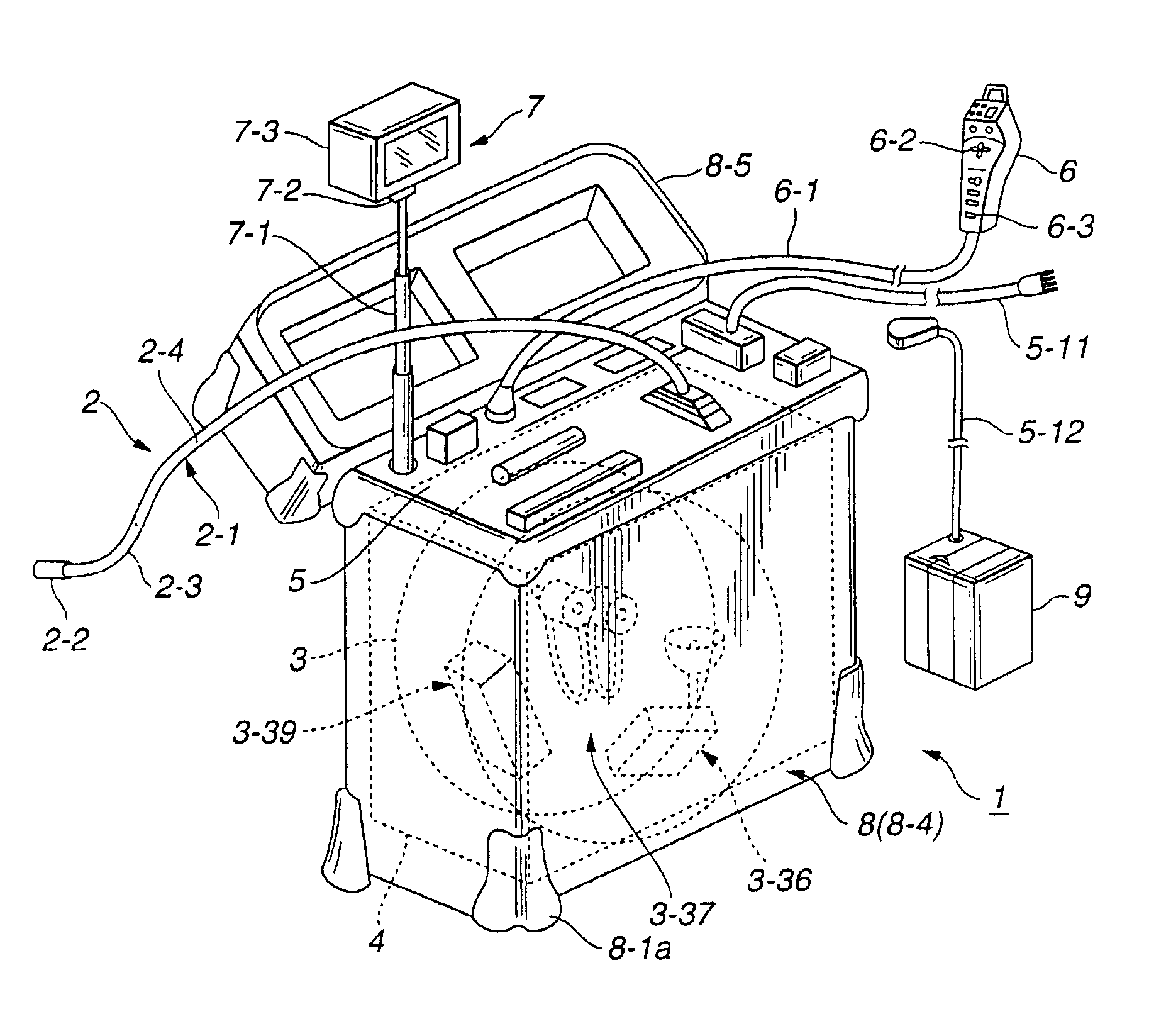
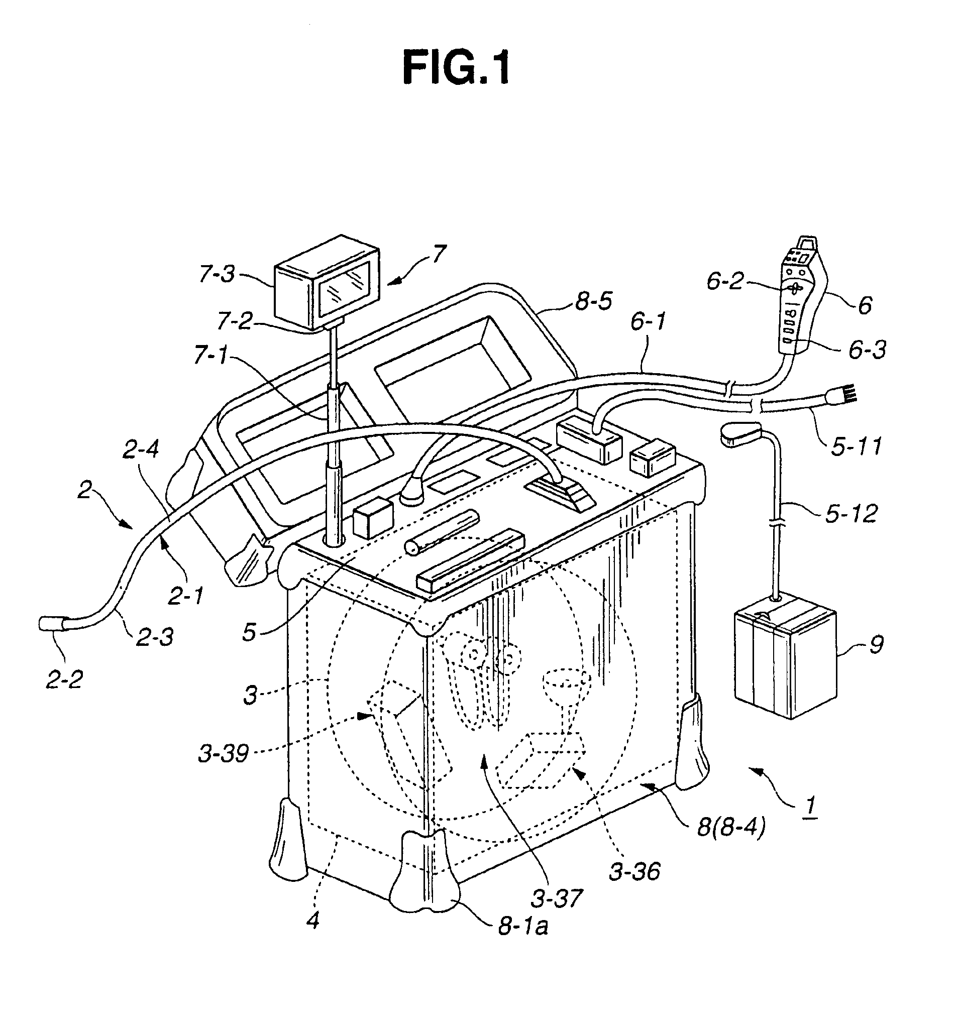
[0148]A first embodiment of the present invention will be described with reference to FIG. 1 to FIG. 24.

[0149]As shown in FIG. 1, a drum-inclusive endoscope system 1 for industrial use in accordance with the first embodiment of the present invention consists mainly of an endoscope 2 for industrial use, a drum 3, a frame 4, a front panel 5, a remote controller 6, a liquid-crystal monitor unit 7, and a stowage case (hereinafter case) 8. Various switches and connectors, and an exhaust vent and an intake vent are exposed on the front panel 5.

[0150]The industrial endoscope 2 has an elongated insertion member 2-1 that is flexible. The drum 3 has a cylindrical shape, and the elongated insertion member 2-1 is wound about the periphery (outer circumference) of the drum 3. The frame 4 rotatably holds the drum 3 freely. The front panel 5 is placed on the top of the frame 4. The remote controller 6 is connected to the front panel 5 by way of a cable 6-1. The liquid cryst...

second embodiment

[0384](Second Embodiment)

[0385]Next, a second embodiment of the present invention will be described with reference to FIG. 33 and FIGS. 34A and 34B. The present embodiment is identical to the first embodiment in terms of the system configuration. However, an operation program employed in the present embodiment is different from that in the first embodiment. Whether the light source lamp 44 should be activated or inactivated is controlled based on the wound state of the insertion member 2-1.

[0386]Specifically, in the endoscope system 1 of the first embodiment, when the insertion member 2-1 is nearly wound up about the drum 3 and stowed in the housing, analog data acquired at the sliding variable resistor 4-20 and transferred from the number-of-drum rotations sensing mechanism to the system control CPU 42 falls within a range leading to the judgment that the light source lamp 44 should be inactivated. The system control CPU 42 temporarily freezes issuance of an activation instruction ...

third embodiment

[0398](Third Embodiment)

[0399]A third embodiment of the present invention will be described with reference to FIG. 35. The present invention is identical to the first embodiment in terms of the system configuration. Action programs employed in the present embodiment are partly different from those employed in the first embodiment.

[0400]Specifically, in the endoscope system 1 of the first embodiment, when the insertion member 2-1 is wound about the drum 3 at the completion of an inspection, the motor-driven angling control circuit unit 3-38 issues a bending section locking instruction to the motor 37a. The bending section locking instruction instructs that the bending section should be held bent. When an attempt is made to stow the insertion member with the bending section 2-3 held bent, the number of rotations of the drum 3 acquired at the sliding variable resistor 4-20 exceeds the threshold from which it is judged whether motor-driven angling is enabled or disabled. When the number...


PUM


Abstract

According to the present invention, an endoscope system having an insertion member thereof wound about a drum comprises an electronic endoscope, a drum, an angling input unit, a motor-driven angling unit, a camera control unit, a motor-driven angling control circuit unit, and a stowage case. A bending section included in an insertion member of the electronic endoscope is motor-driven to bend, and a solid-state imaging device is incorporated at the tip of the insertion member. The insertion member is wound about the periphery of the drum. The angling input unit is separated from the electronic endoscope, and used to enter a direction of bending in which a user wants to bend the bending section. The motor-driven angling unit is incorporated in the drum, and includes a driving source for driving a driving mechanism that drives the bending section. The camera control unit controls the solid-state imaging device, and includes a signal processor for processing an electric signal sent from the solid-state imaging device to generate a video signal. The motor-driven angling control circuit unit controls the movement of the bending section. The drum is rotatably stowed in the stowage case freely.

Description

CROSS-REFERENCE TO RELATED APPLICATIONS[0001]This is a continuation of U.S. patent application Ser. No. 09 / 808,807 filed on Mar. 15, 2001.[0002]This application claims benefit of Japanese Application No. 2000-72816 filed in Japan on Mar. 15, 2000, No. 200072814 filed in Japan on Mar. 15, 2000, No. 2000-72815 filed in Japan on Mar. 15, 2000, No. 2001-5568 filed in Japan on Jan. 12, 2001, No. 2001-5567 filed in Japan on Jan. 12, 2001, Hei10-261767 filed in Japan on Sep. 16, 1998, the contents of which are incorporated these references.BACKGROUND OF THE INVENTION[0003]1. Field of the Invention[0004]The present invention relates to an endoscope system having a drum, about which an insertion member of an endoscope is wound, stowed in a case.[0005]2. Related Art Statement[0006]An endoscope system having an insertion member elongated to be so long as to enable endoscopic inspection of a deep part of a plant is sometimes used as an endoscope system for industrial. In this case, if the elong...

Claims


Application Information

Patent Timeline
Patent Type & Authority Patents(United States)
IPC IPC(8): A61B1/00A61B1/005A61B1/05B65H75/40B65H75/44
CPCA61B1/0052A61B1/05B65H75/40A61B1/0016B65H75/4484B65H75/4486B65H75/4471B65H75/4402A61B1/06
Inventor HASEGAWA, HIROSHIKIMURA, SEIJISARUYA, NOBUYUKIFUJIKAWA, SHINJIISHIGAMI, TAKAKAZUKUMAKURA, MASAHIROSHIMOE, YASUFUMI
Owner OLYMPUS CORP
Why Eureka
Try Eureka