Head-up display

a display and head-up technology, applied in the field of head-up displays, can solve the problems of difficult molding of blocks, inability to meet the requirement of compact design, and increase the size of optical units

Inactive Publication Date: 2004-12-28
DENSO CORP
View PDF11 Cites 87 Cited by
  • Summary
  • Abstract
  • Description
  • Claims
  • Application Information

AI Technical Summary

Benefits of technology

Consequently, the problem wherein images formed with light rays having different wavelengths and having passed through a prism are seen at different points can be solved. Since the prism is located on a light path, an optical unit can be designed compactly. Consequently, a head-up display capable of presenting a large-size virtual image without deterioration in display definition can be realized at low cost.
According to the twelfth aspect of the present invention, a head-up display has a prism sheet that also serves as a dustproof cover. A dedicated dustproof cover can therefore be excluded. Consequently, an optical unit can be designed compactly, and the cost of the head-up display can be reduced.

Problems solved by technology

This leads to an increase in the size of the optical unit.
Furthermore, since a large number of deflecting means is employed, the requirement of a compact design cannot be met because of the space needed to accommodate the deflecting means.
Furthermore, it is very difficult to mold the block so that the block is optically homogeneous.
This makes it hard to present a large-size image far away.
When the distance to an image in a direction horizontal to the eyes is noticeably different from the distance thereto in a direction vertical thereto, an observer may feel uncomfortable, like in the case of car-sickness.
This is a problem with a display.
Thus, an observer can hardly recognize the separation.
However, in this case, a drawback described below may ensue.
This leads to a drastic deterioration in display quality.

Method used


Image

  • Head-up display
  • Head-up display
  • Head-up display

Examples


first embodiment

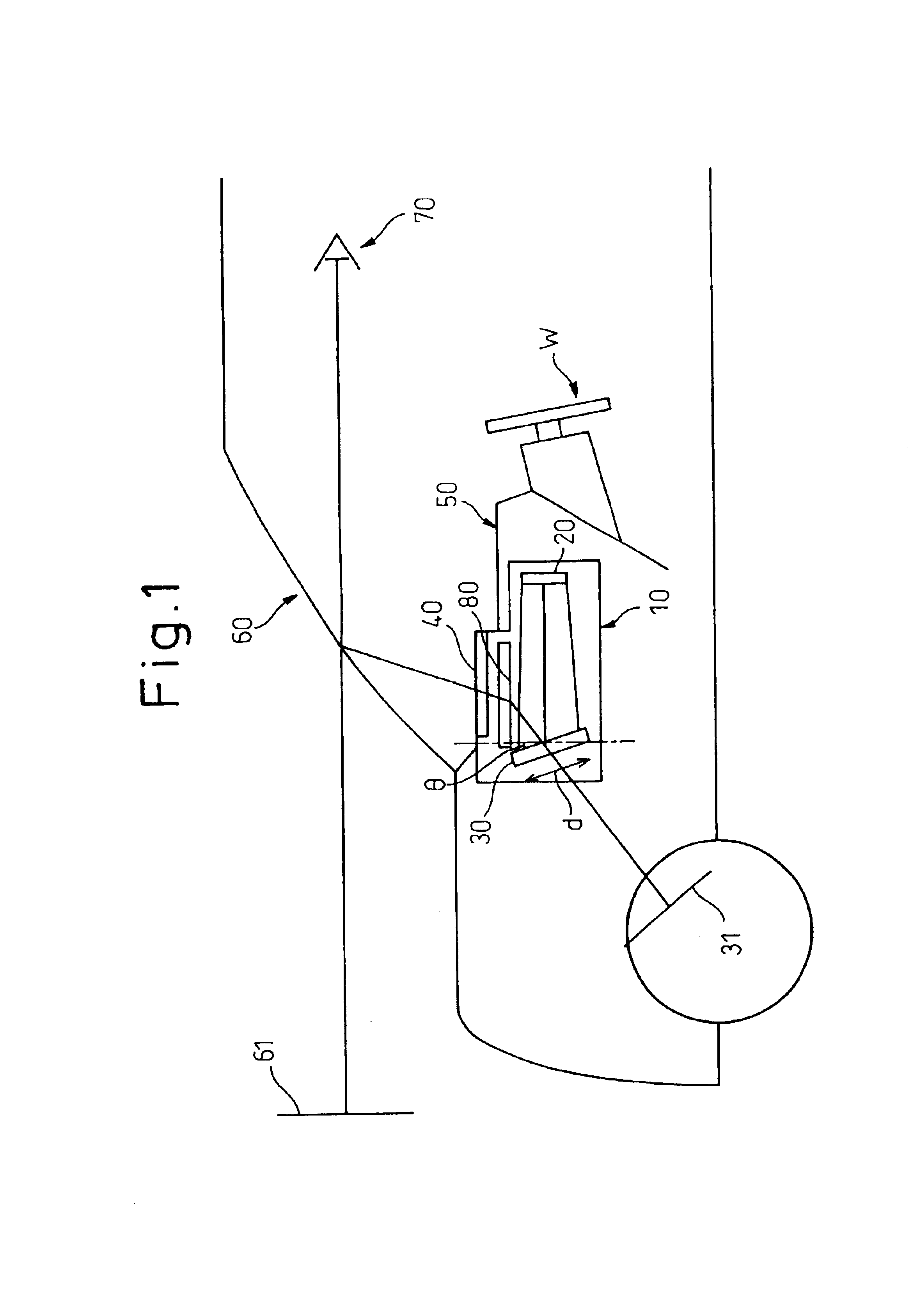
An example of the present invention will be described in conjunction with FIG. 1, FIG. 2, FIG. 8, and FIG. 9. FIG. 1 shows a case where a head-up display according to the present invention is adapted for a motorcar.

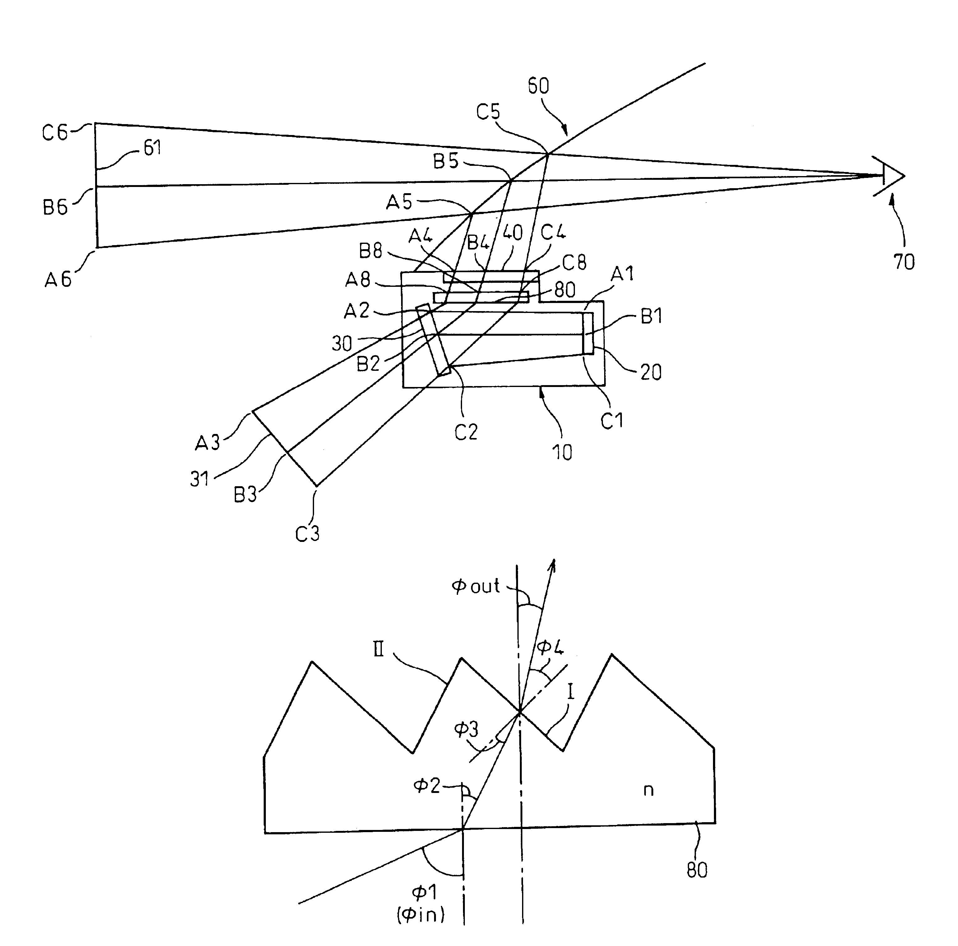
The head-up display includes an optical unit 10. The optical unit 10 includes a display device 20, a reflecting mirror (concave mirror) 30, and a prism sheet 80. A dustproof cover 40 made of, for example, a transparent resin is laid over an opening formed in the optical unit 10. The dustproof cover 40 may be mounted independently of the prism sheet 80 or the prism sheet 80 may be used as the dustproof cover 40.

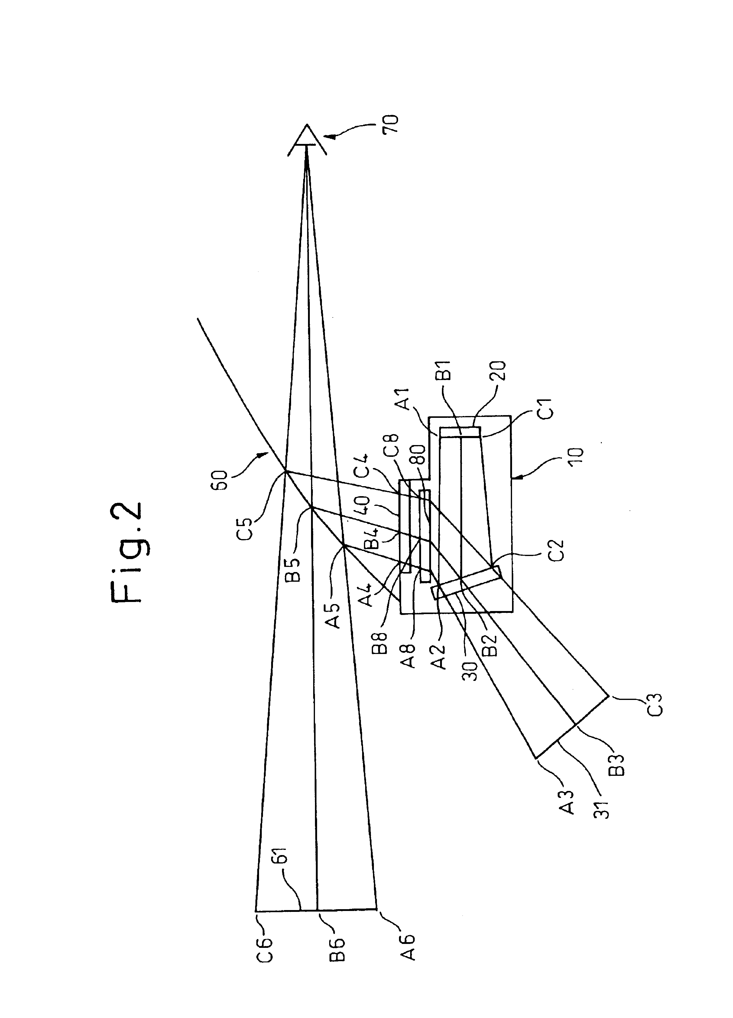
Light emitted from the display device 20 is reflected from the concave mirror 30, and refracted through the prism sheet 80. The light is then incident on a windshield 60. When the incident light is reflected by the windshield 60, the windshield 60 presents display information (picture information) as a virtual image 61 formed ahead of a vehicle. Herein, the concave ...

second example

The second example has the same advantages as the first example while employing a plurality of display devices. Referring to FIG. 10, the second example will be described below.

Referring to FIG. 10, an optical unit includes a display device 21 on which an image that emits light having a wavelength .lambda.1 is displayed and a display device 22 on which an image that emits light having a wavelength .lambda.2 is displayed. Furthermore, the optical unit includes a reflecting mirror 31 that reflects light emitted from the display device 21, and a half mirror 32 through which passes the light coming from the display device 21 and which reflects light coming from the display device 22. The display devices 21 and 22, reflecting mirror 31, and half mirror 32 are arranged so that a distance d between a virtual image of the display device 21 formed by the reflecting mirror 31 and a virtual image of the display device 22 formed by the half mirror 32 satisfy the equation (2) described in relati...

third example

The third example will be described in conjunction with FIG. 11 and FIG. 12. Light characteristics of the spectral distribution shown in FIG. 11 is emitted as light rays having different wavelengths from the display device 20 included in the first example. Referring to FIG. 11, light that is plotted as an acute curve in the center of FIG. 11 will be described as a typical example. The center wavelength of the light plotted as the acute curve is .lambda. and the half width of the acute curve is .DELTA..lambda.. The points on the curve determining the half width indicate wavelengths of .lambda.3 and .lambda.4 that are expressed as follows:

.lambda.3=.lambda.-.DELTA..lambda. / 2

.lambda.4=.lambda.+.DELTA..lambda. / 2

The light having the center wavelength .lambda. and the half width .DELTA..lambda. travels, as shown in FIG. 12, between light having the wavelength of .lambda.3 and light having the wavelength of .lambda.4 and reaches a view point.

Assuming that an angle of incidence of the light...


PUM


Abstract

Provided is a head-up display having a prism sheet interposed between a display device and the position of an observer's eye. Control is extended so that points from which light rays having different wavelengths emerge are made different by a predetermined distance from each other so as not to form images at different points by light rays from a point source, relative to the difference between the wavelengths. Otherwise, a distance to an image in a vertical direction is made shorter by a predetermined distance than a distance thereto in a horizontal direction. The vertical angle of each of prisms included in the prism sheet is asymmetrical to a normal to the surface of the prism sheet.

Description

1. Field of the InventionThe present invention relates to a head-up display, more particularly, to a head-up display adaptable for use in vehicles or motorcars.2. Description of the Related ArtDemand for human-machine interfaces of images that are excellently discernible and impose little burden on a driver is expected to increase due to the diversity in in-vehicle display information and the plentifulness thereof. In particular, the need for a field of safe driving aid in which view assistance information, visual information, and others are given as the contents of display is expected to increase. For effective communication of the information, preferably, a head-up display capable of presenting a large-size image far away, and superposing one image on another is expected to be adopted.The head-up display includes an optical unit placed on an installment panel in a vehicle compartment. The optical unit consists mainly of a display device such as a liquid crystal display or a CRT, a...

Claims


Application Information

Patent Timeline
Patent Type & Authority Patents(United States)
IPC IPC(8): G02B27/01
CPCG02B27/0101
Inventor FUJIKAWA, TAKAYUKIANDO, HIROSHIKAKIZAKI, MASARUYASUDA, KAZUYA
Owner DENSO CORP
Why Eureka
Try Eureka