Imaging device and method, computer program product on computer-readable medium, and imaging system

a computer-readable medium and imaging system technology, applied in the field of imaging devices and methods, can solve the problems of inability to know the details of an intrusion, difficulty in finding such an intruder, and inability to find such an intruder, so as to prevent the overlooking of any slight motion

Inactive Publication Date: 2008-12-02
SONY CORP
View PDF7 Cites 7 Cited by
  • Summary
  • Abstract
  • Description
  • Claims
  • Application Information

AI Technical Summary

Benefits of technology

[0041]According to the present invention, a color image corresponding to an imaging position of an object in a panoramic color image is overlaid on an infrared image obtained by imaging the object by infrared radiation measurement with the imaging direction being controlled to a desired one in an imaging range to produce a synthetic image to be displayed. Therefore, an area where the object exists can be displayed as a luminance distribution of the infrared image even at night, and thus the position of the area where the object exists in a relation with its background as well can definitely be identified. Also, since it is possible to prevent overlooking of any slight motion of a human being, the prevent invention permits a higher-definition surveillance / monitoring.

Problems solved by technology

In case such a surveillance camera is installed in an off-limits area (restricted area), it will be the most important problem to make a “most efficient and pinpoint” imaging of only a person or the like going into such an off-limits area.
Further, since the surveillance / monitoring system depends on the observer's eyes, he or she may possibly fail to find such changes of a scene.
Especially, in case the range of a scene under surveillance is wider, it is extremely difficult to find such an intruder.
Furthermore, since the image captured by the camera at night is so dark itself that it is not possible to know details of an intrusion, that is, from which part of which building a person has entered the off-limits area or through which route the intruder has moved.
The wider the range of a scene under surveillance, the more difficult it is to know the above details.

Method used


Image

  • Imaging device and method, computer program product on computer-readable medium, and imaging system
  • Imaging device and method, computer program product on computer-readable medium, and imaging system
  • Imaging device and method, computer program product on computer-readable medium, and imaging system

Examples


Embodiment Construction

[0051]The present invention will be described in detail below concerning embodiments thereof with reference to the accompanying drawings.

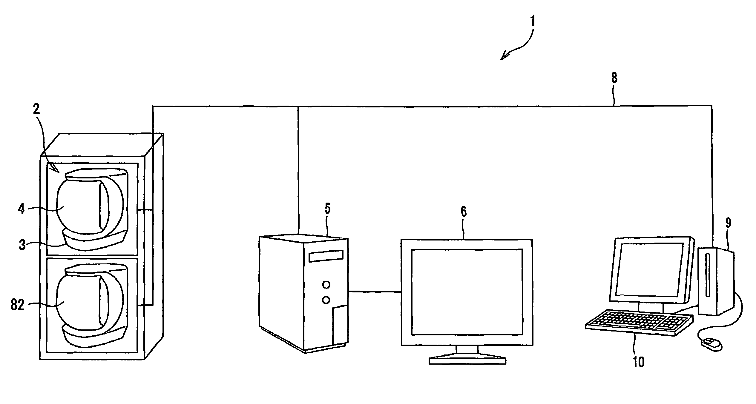
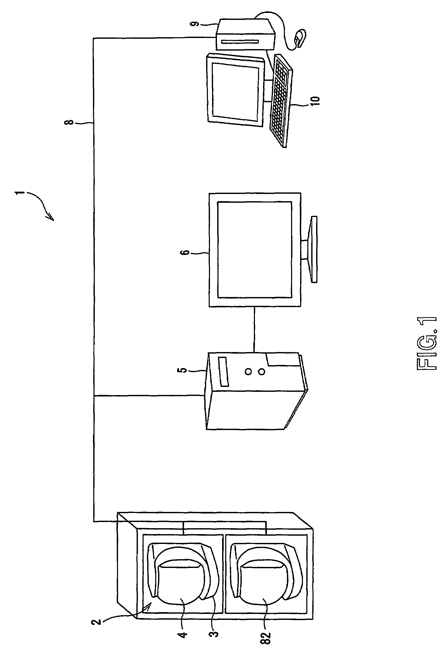
[0052]The present invention is applied to a surveillance / monitoring system 1 constructed as shown in FIG. 1, for example.

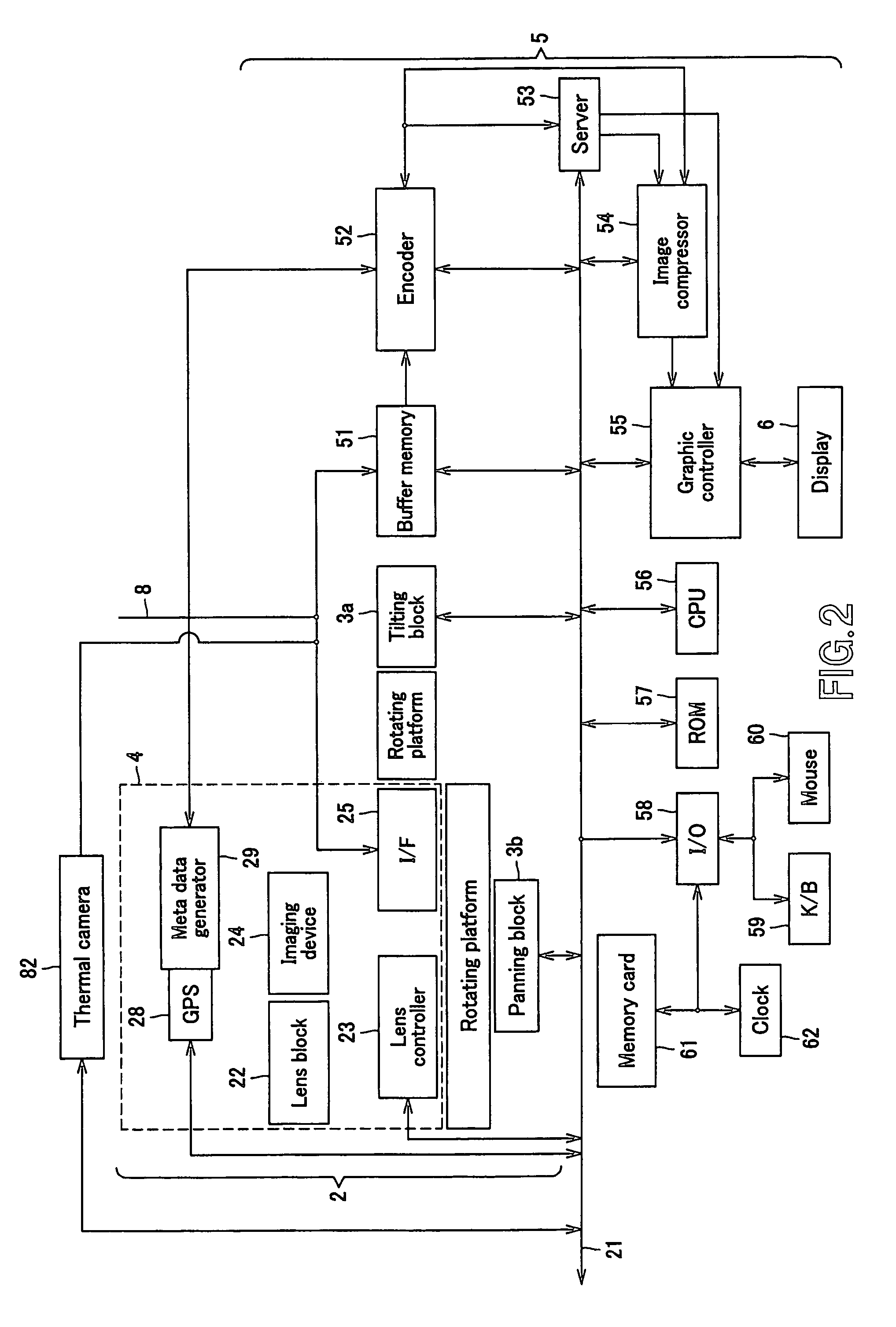
[0053]The surveillance / monitoring system 1 includes a visible-light color camera unit 2 to produce an image signal by imaging an object, infrared camera 82, monitor 5 supplied with the image signal from at least the color camera unit 2, display 6 connected to the monitor 5, terminal unit 9 used by a plurality of users to execute their applications, terminal display 10 connected to the terminal unit 9, and a network 8 to make two-way communications among the color camera unit 2, monitor 5 and terminal unit 9.

[0054]Of the surveillance / monitoring system 1, the color camera unit 2 is an integration of a pan / tilter 3 and camera block 4. The pan / tilter 3 is formed as a rotating platform that can be turned about tilting and panning axes...


PUM


Abstract

An imaging device and methodology for sequentially adjusting an imaging direction to generate color unit images that together form a color panoramic image are provided. The imaging direction is sequentially adjusted to generate infrared unit images that together form an infrared panoramic image. The color panoramic image is produced by overlaying the color unit images, one color unit image on another, and the infrared panoramic image is produced by overlaying the infrared unit images, one infrared image on another. A resultant image is synthesized from the color panoramic image and the infrared panoramic image by overlaying, on an infrared image of an object, a color image corresponding to the location where the object has been imaged in infrared, and the resultant image is displayed.

Description

CROSS REFERENCES TO RELATED APPLICATIONS[0001]The present invention contains subject matter related to Japanese Patent Application JP 2005-154445 filed in the Japanese Patent Office on May 26, 2005, the entire content of which is incorporated herein by reference.BACKGROUND OF THE INVENTION[0002]1. Field of the Invention[0003]The present invention relates to an imaging device and method, computer program product on a computer-readable medium and an imaging system, for surveillance of a wide-range scene by means of a panoramic image obtained by imaging with sequential shifting of the imaging direction.[0004]2. Description of the Related Art[0005]In the electronic still cameras having been used widely in the past, light having passed through a lens by releasing the shutter of the camera to image an object can be converted into an image signal by a solid-state image sensor such as CCD (charge-coupled device) and the image signal be recorded to a recording medium. The image signal once r...

Claims


Application Information

Patent Timeline
Patent Type & Authority Patents(United States)
IPC IPC(8): G02B26/10
CPCH04N5/23238H04N5/2624H04N5/332H04N23/698H04N23/11
Inventor IKEDA, YUKIO
Owner SONY CORP
Why Eureka
Try Eureka