Precision motion transducer utilizing elasticity ratio

Inactive Publication Date: 2006-07-20
IND TECH RES INST
View PDF6 Cites 2 Cited by
  • Summary
  • Abstract
  • Description
  • Claims
  • Application Information

AI Technical Summary

Benefits of technology

[0007] In the light of forgoing drawbacks, an objective of the present invention is to provide a

Problems solved by technology

However, these positioning control devices are restricted to their own structures and therefore have many drawbacks, such

Method used


Image

  • Precision motion transducer utilizing elasticity ratio
  • Precision motion transducer utilizing elasticity ratio
  • Precision motion transducer utilizing elasticity ratio

Examples


first embodiment

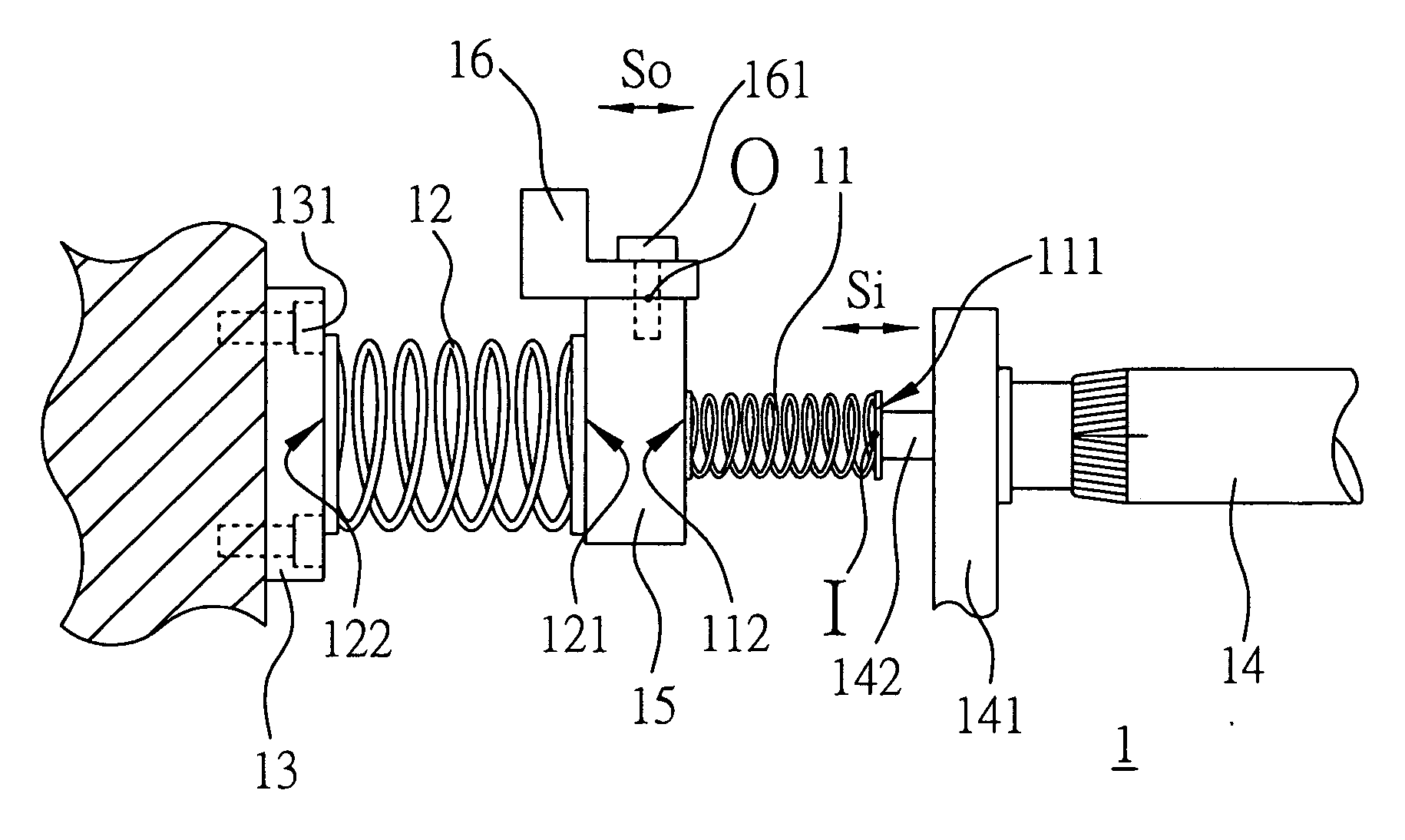
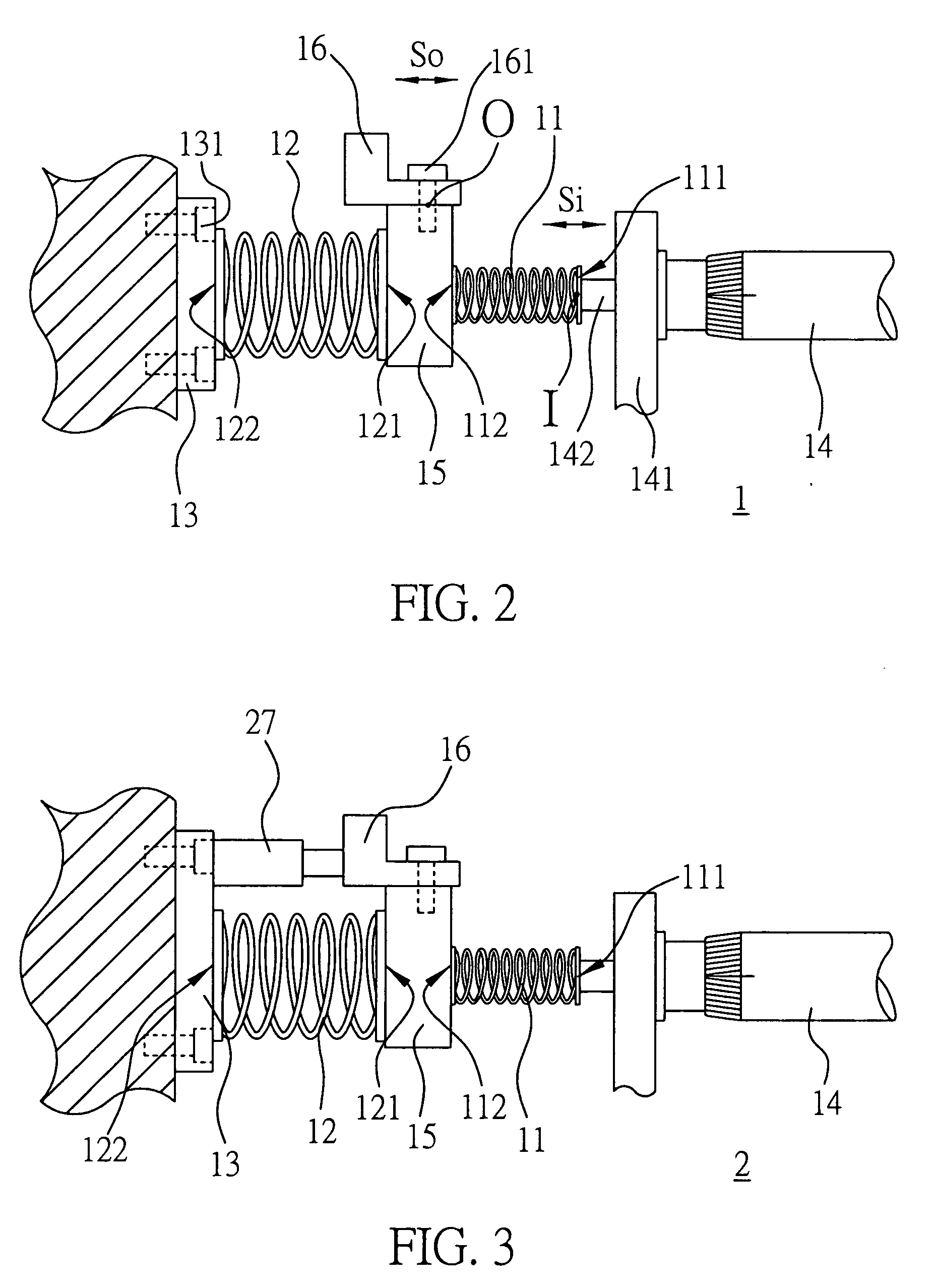
[0031]FIG. 2 is a side view showing a precision motion transducer according to the first embodiment of the present invention. As shown in FIG. 2, the precision motion transducer 1 comprises: a first spring 11 provided with a first end 111 and a second end 112; a second spring 12 provided with a free portion 121 and a fixed portion 122; a fixing means 13 for fixing the fixed portion 122 of the second spring 12 to a base (without numeral) by a plurality of screws 131; a micrometer 14 used as a motion input means for inputting linear motion, the micrometer 14 being fixed onto the base by a fixing means 141; a connecting means 15 for connecting the free portion 121 of the second spring 12 with the second end 112 of the first spring 11; and a motion output means 16 fixed onto the connecting means 15 by screws 161. The first spring 11 is provided with a first modulus of elasticity K1, and the second spring 12 is provided with a second modulus of elasticity K2.

[0032] When the micrometer 1...

third embodiment

[0041]FIG. 4 is a perspective view showing a precision motion transducer according to the third embodiment of the present invention. The precision motion transducer according to the third embodiment of the present invention is a modification of the precision motion transducer according to the first embodiment, and hence the same structures and functions will not be described in detail redundantly, only the differences between the first and third embodiments will be described.

[0042] As shown in FIG. 4, the precision motion transducer 3 comprises: a first spring 31 provided with a first end 311 and a second end 312; a second spring 32 provided with a free portion 321 and a fixed portion 322; a fixing means 33 for fixing the fixed portion 322 of the second spring 32 to a base (without numeral); a stepping motor 34 used as a motion input means for inputting rotational motions, the stepping motor 34 being fixed onto the base by a fixing means 341; a connecting means 35 for connecting th...

fourth embodiment

[0049]FIG. 5 is a side view showing a precision motion transducer according to the fourth embodiment of the present invention. The precision motion transducer according to the fourth embodiment of the present invention is a modification of the precision motion transducer according to the first embodiment, and hence the same structures and functions will not be described in detail redundantly. In FIG. 5, same or similar structures are represented by same numerals as in FIG. 2.

[0050] As shown in FIG. 5, in the precision motion transducer 4, an ends-fixed beam 42 is used to replace the second spring 12 in the first embodiment. In the ends-fixed beam 42, a central portion 421 is used as the free portion, and two end portions 422 are used as the fixed portions. There are fixing means 43 respectively provided at the two end portions of the ends-fixed beam 42, so as to respectively fix the fixed portions 422 of the ends-fixed beam 42 onto a base (not shown). The second end 112 of the firs...


PUM


Abstract

A precision motion transducer is provided in the present invention. The precision motion transducer is provided with a first elastic body. An end of the first elastic body is connected to an end of a second elastic body, while the other end of the second elastic body is fixed to a base via a fixing means. A motion input means is connected to the other end of the first elastic body for inputting motion inputs, while a motion output means is provided at a location where the first elastic body is connected with the second elastic body for outputting motion outputs. The modulus of elastic of the first elastic body is smaller than the modulus of elastic of the second elastic body, whereby relatively large motion inputs can be converted to more precise and finer motion inputs, so as to attain precise positioning control.

Description

FIELD OF THE INVENTION [0001] The present invention relates to a precision motion transducer, and more particularly, to a precision motion transducer for performing a precision motion conversion utilizing an elasticity ratio between a plurality of elastic bodies. BACKGROUND OF THE INVENTION [0002] Recently, micro-scale manufacturing technologies, even nano-scale manufacturing technologies have been gradually applied in various technical fields such as semiconductor, optoelectronics, biomedicine, precision machine and the like, and hence a positioning control technology with high accuracy and fine adjustment which can fulfill requirements of various precision processes is desirable. Moreover, in precision measurement instruments such as optical measurement instruments, it is necessary to perform accurate position adjustments to the instruments to achieve desired performances or functions. For example, in testing instruments for a solid immerse lens (SIL) near-field optical head, a pr...

Claims


Application Information

Patent Timeline
IPC IPC(8): B23Q16/00
CPCB82Y35/00Y10T74/18992G02B7/004G01Q10/04
Inventor LEE, KWEN-JIN
Owner IND TECH RES INST
Why Eureka
Try Eureka