
Image processing apparatus and image processing method thereof

a technology which is applied in the field of image processing apparatus and image processing method thereof, can solve the problems of missing high-frequency component of image, inability to change the display of progressive image, and inability to clearly specify the portion of imag

Inactive Publication Date: 2013-01-01
CANON KK
View PDF18 Cites 3 Cited by
  • Summary
  • Abstract
  • Description
  • Claims
  • Application Information

AI Technical Summary

Benefits of technology

The invention allows for the creation of a progressive image with small motion between field images. This technology can clearly specify the part of the image that is moving the most, so that the user can create a smooth transition between images.

Problems solved by technology

However, according to the above technology, when viewing a generated progressive image, in many cases, a user cannot visually recognize that in the portions of a large motion between the field images, a high-frequency component of the image is missing.
Further, there is a problem that it is impossible to change a display of the progressive image according to the motion between the field images.
Further, it is impossible to clearly specify the portion in the image having the large motion so that a user can identify the portion.

Method used


Image

  • Image processing apparatus and image processing method thereof
  • Image processing apparatus and image processing method thereof
  • Image processing apparatus and image processing method thereof

Examples


Embodiment Construction

[0026]Various exemplary embodiments, features, and aspects of the invention will be described in detail below with reference to the drawings.

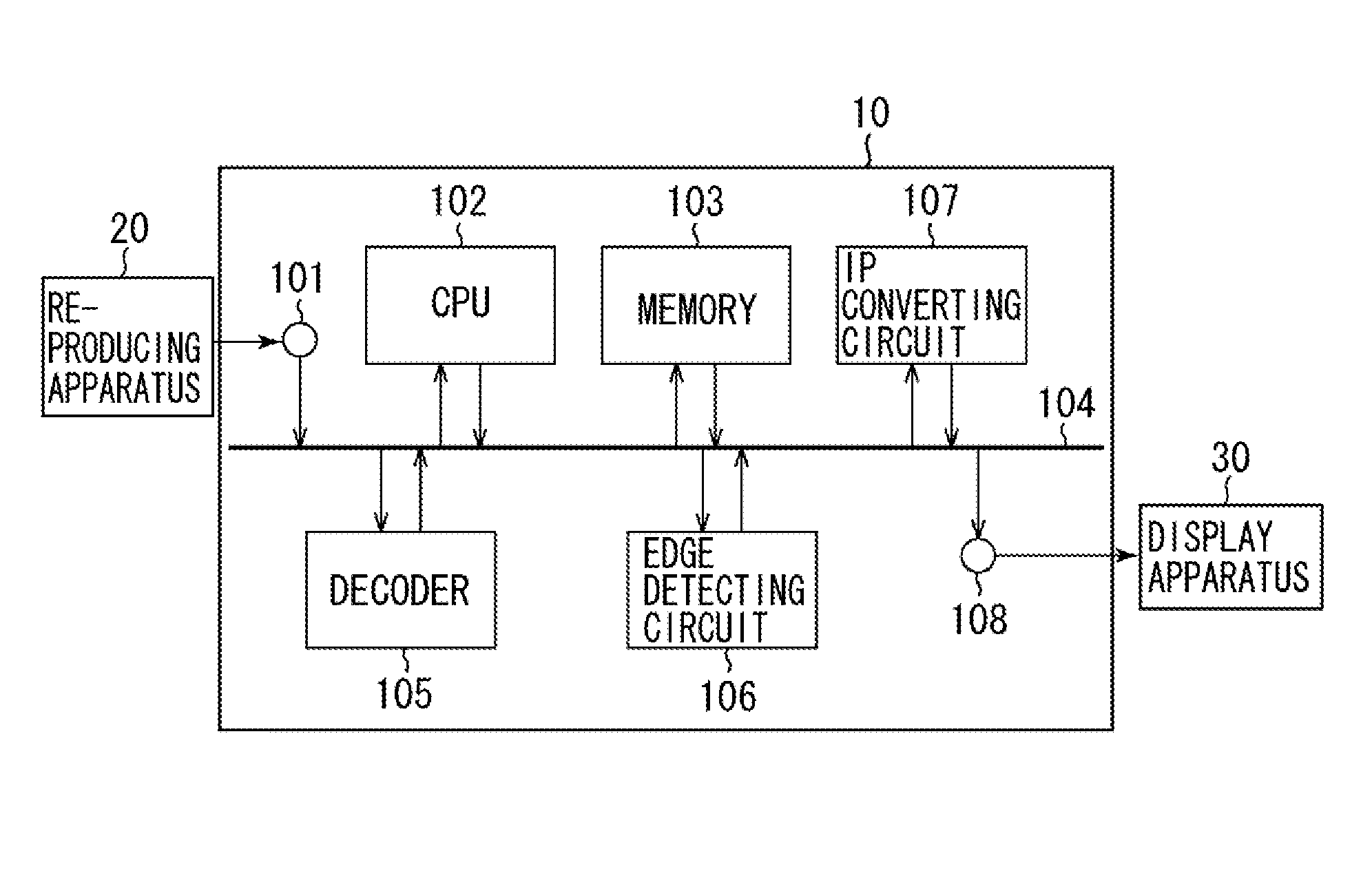
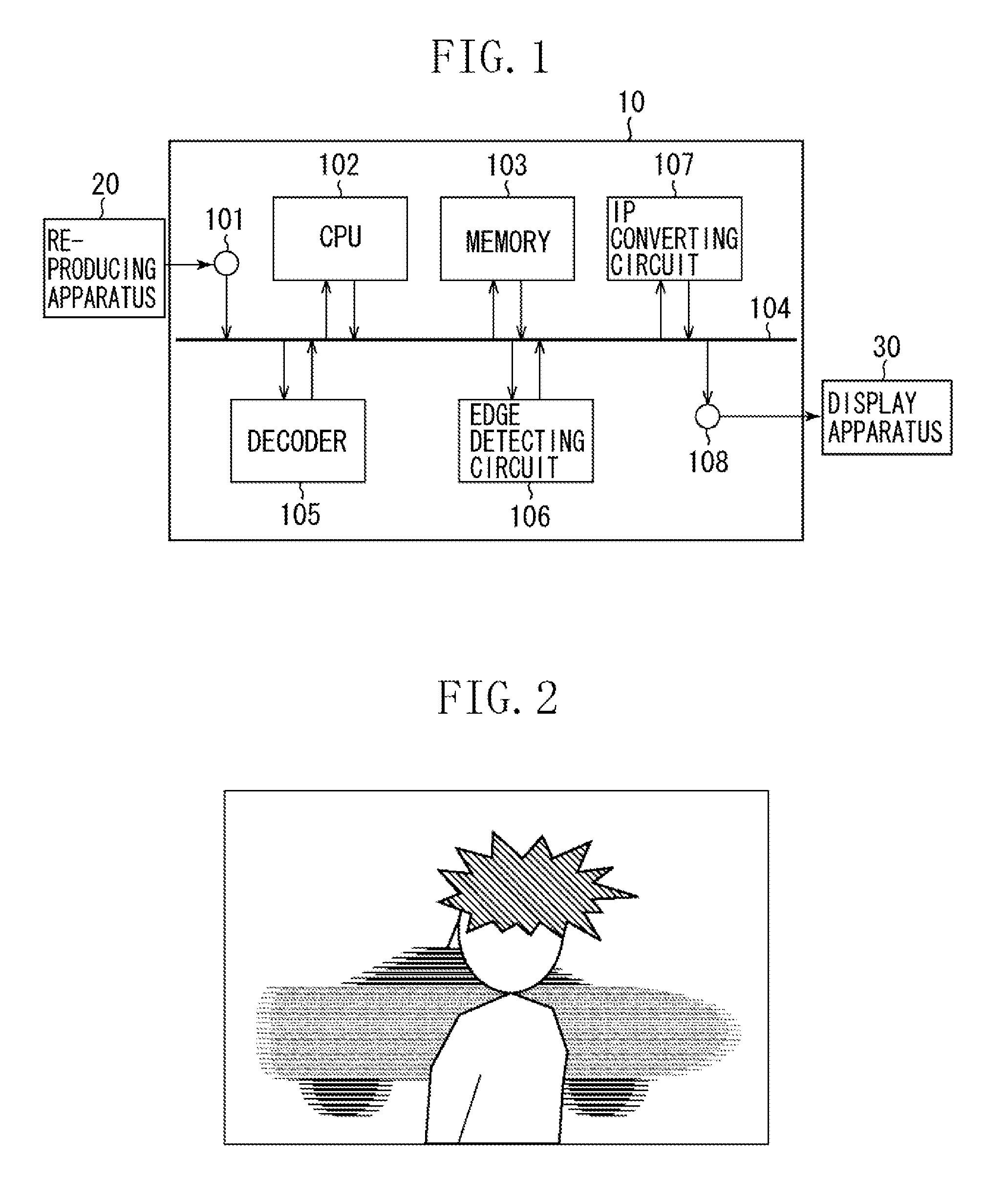
[0027]FIG. 1 is a block diagram illustrating an example of a configuration of an image processing apparatus 10 according to an exemplary embodiment of the present invention.

[0028]In FIG. 1, a reproducing apparatus 20 is connected to an input terminal 101 in the image processing apparatus 10, and a display apparatus 30 is connected to an output terminal 108 in the image processing apparatus 10.

[0029]Image data obtained by interlace scanning is input from a reproducing apparatus 20 to an input terminal 101. The image processing apparatus 10 includes a control circuit (central processing unit (CPU)) 102, a memory 103, a data bus 104, a decoder 105, an edge detecting circuit 106, and an interlace-progressive converting circuit (IP converting circuit)) 107. The IP converting circuit 107 converts image data of the interlace scanning into image data o...


PUM


Abstract

An image processing apparatus detects an amount of pixel motion in a plurality of field images included in interlace image data, and determines a pixel region having a large motion by comparing the amount of the motion of the detected pixel to a predetermined threshold value. An image processing apparatus combines a predetermined pattern with the pixel region that has a large motion and is converted from the interlace image.

Description

BACKGROUND OF THE INVENTION[0001]1. Field of the Invention[0002]The present invention relates to an image processing apparatus and an image processing method thereof, more particularly, a suitable technology that converts an interlace image into a progressive image.[0003]2. Description of the Related Art[0004]When an interlace image that is a moving image is printed or displayed on a display screen as a still image, the interlace image is converted into a progressive image to be printed or displayed as the still image.[0005]It is known that when an interlace-progressive conversion is performed, a motion between field images in the interlace images is calculated, a position of a pixel is adjusted with reference to the motion, and paired field images are combined.[0006]Japanese Patent Application Laid-Open No. 2007-110217 discusses a technology that generates a non-interlace signal by interpolating a line signal into a video signal acquired by interlace scanning and generates an inter...

Claims


Application Information

Patent Timeline
Patent Type & Authority Patents(United States)
IPC IPC(8): H04N11/04H04N11/20
CPCG06T3/403G06T7/2033H04N5/142H04N5/144H04N7/012G06T2207/10016H04N7/0137H04N7/0142G06T7/246
Inventor OISHI, AKIHIRO
Owner CANON KK
Learn More