System and method for current overload response with class D topology

a power supply output and topology technology, applied in the direction of circuit arrangement, emergency protective arrangement for limiting excess voltage/current, pulse technique, etc., can solve problems such as system failure, component damage, and component characteristics that alter, and achieve the effect of reducing power rating, allowing output current regulation, and reducing the number of ratings

Active Publication Date: 2008-12-09
TEXAS INSTR INC
View PDF2 Cites 5 Cited by
  • Summary
  • Abstract
  • Description
  • Claims
  • Application Information

AI Technical Summary

Benefits of technology

[0012]According to an advantage of the present invention, the low side switch in a class D topology coupled to the gate of a power supply output FET is composed of two or more switches to obtain different regulation points for current overload conditions. One of the switches can have a higher power rating and operate to discharge a large voltage from the gate of the power supply output FET. Another switch can have a smaller rating, and be switched on / off to permit output current regulation within a relatively smaller current range. Accordingly, the larger switch is used to discharge high voltages and handle high currents for quickly responding to any current overload condition, while the smaller switch permits a closer tolerance regulation of output current near an overcurrent threshold value. By closely limiting output current during an overcurrent condition, stress on the power supply output FET can be minimized while still powering a power supply load. The reduced stress on the power supply output FET permits the FET to have a greater longevity, and reduced rating, thereby reducing cost of the power supply.
[0013]According to an advantage of the present invention, a timer is supplied in a control circuit for determining a length of time a large rating switch can be switched to the gate of the power supply output FET to draw off gate voltage and reduce output current. In addition, or alternately, a timer is supplied that determines the length of time the overload current response circuit operates before shutting down the power supply output FET. For example, the timers can be used to determine a length of time an overload condition can exist prior to latching off the power supply output FET to protect the FET and the load from damage or failure.
[0014]According to an advantage of the present invention, the backplane power supply is protected from disruptions due to current overload conditions by sensing excessive load current through a sense resistor in comparison with a reference voltage. When excessive load current is sensed, the gate voltage of the power switch is pulled down to discharge the gate capacitor. Once the load current drops to a desired level, the gate voltage on the power switch is allowed to rise once again, to avoid shutting off the power switch completely. If the overload current condition clears, normal operation resumes, permitting the power switch to operate in an enhanced mode. If another current overload condition is detected, the cycle repeats.
[0015]The present invention provides a rapid response to a current overload condition, while returning the backplane power supply to normal operating parameters within a short interval. The minimal interruption in power supplied to the load improves power supply performance. The current supply to the load is also maintained at a more constant level. In the event of a catastrophic load failure, the current drawn from the backplane supply is regulated until the power switch is shut off to avoid disruptions on the backplane supply.
[0016]According to another aspect of the present invention, the overload current control circuit can be provided as part of a hot pluggable switch that is plugged into the backplane power supply under powered conditions.

Problems solved by technology

Overcurrent conditions can lead to component damage, alter component characteristics or cause system failures, for example.
One conventional response to overload conditions in a power switch is to rapidly shut down the power switch, typically leading to a power shut down in the load coupled to the power switch.
Retry timer 24 may not be able to handle power spikes with differing characteristics, or may cause a power oscillation when system noise causes the current overload detector to trip.
Op-amp 33 contributes to controlling current provided to the load, but has a slow response time, which may result in excessive current flow.
Another drawback of the design of circuit 30 is that the slow response time of op-amp 33 may permit excessive current to flow causing a drop in the backplane voltage supply.
It can also be difficult to construct linear op-amp 33 to have stable operation over a wide range of control parameters.

Method used


Image

  • System and method for current overload response with class D topology
  • System and method for current overload response with class D topology
  • System and method for current overload response with class D topology

Examples


Embodiment Construction

[0025]In the following description, the phrases “turning on” and “turning off,” and similar terminology, can refer to the process of turning a switch on or off, such as urging a switch further toward a completely “on” state or a completely “off” state. Also, an “on” state is meant to indicate that the switch is conducting, while an “off” state indicates non-conductance or blocking.

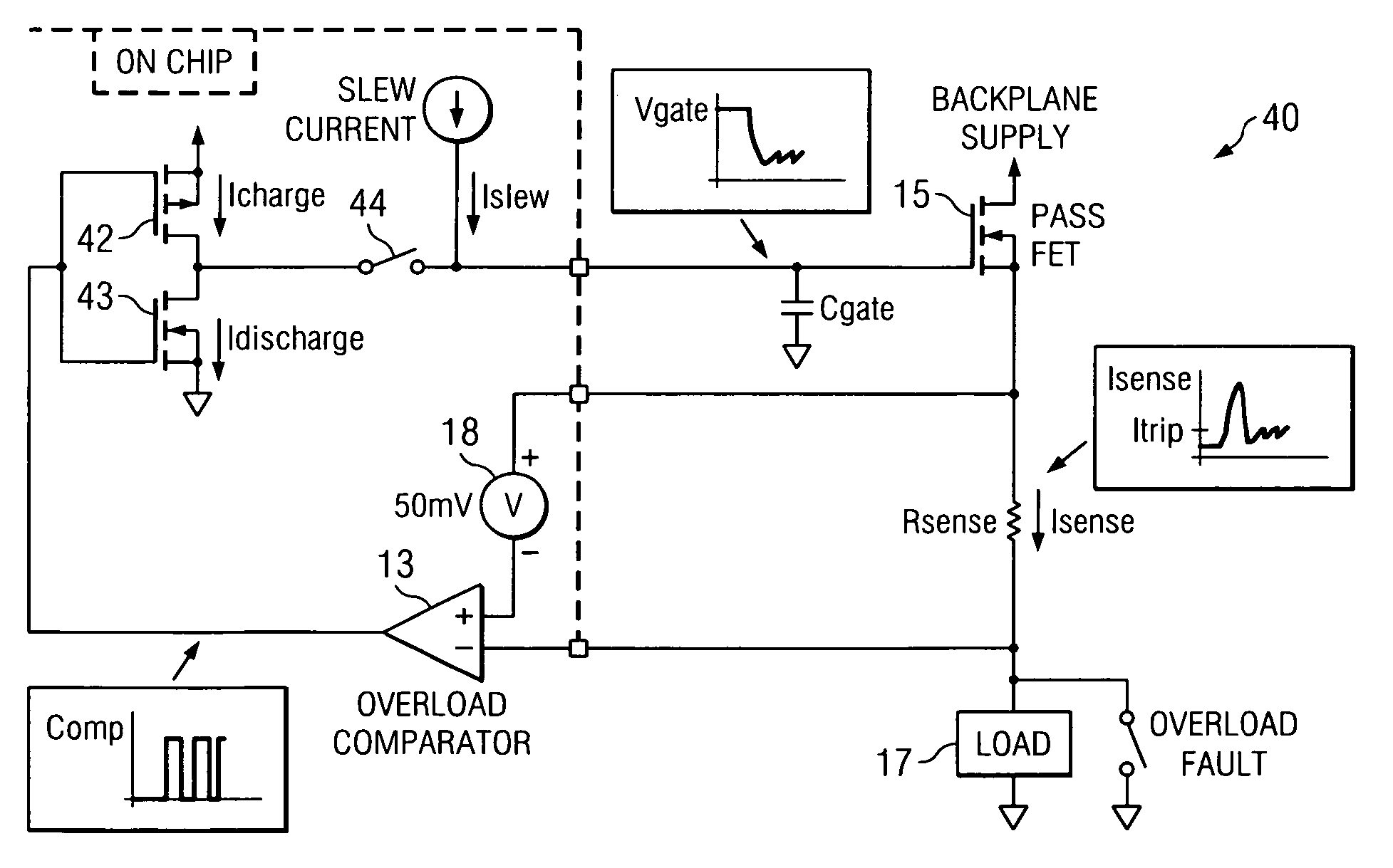
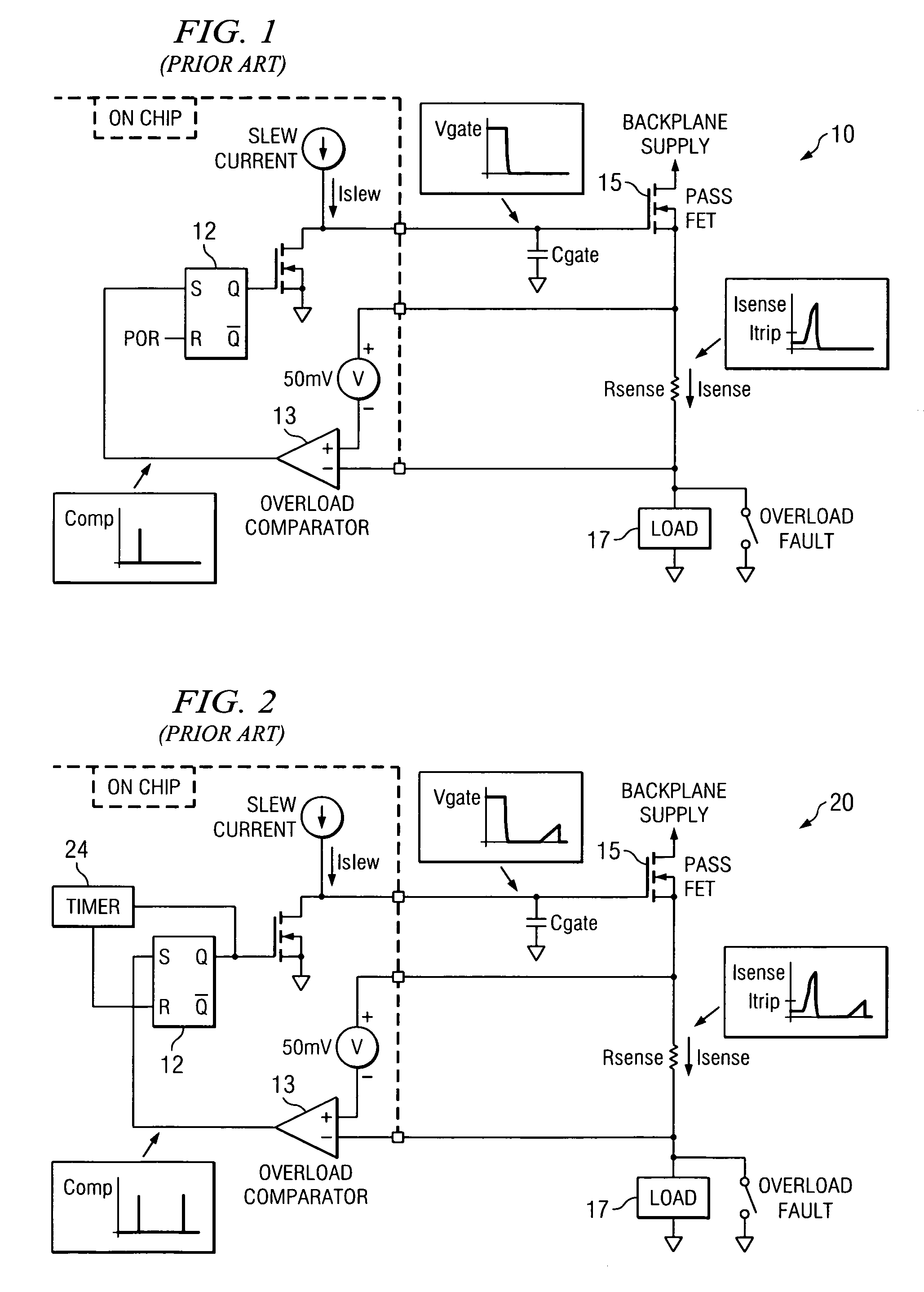
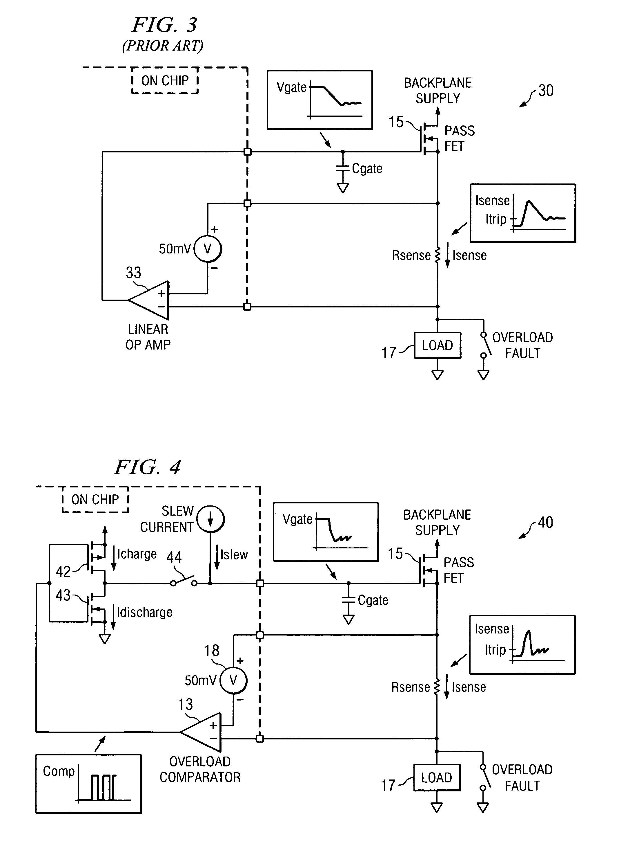
[0026]Referring now to FIG. 4, a circuit 40 is illustrated for providing a control response to a current overload condition in accordance with the present invention. Circuit 40 includes overload comparator 13 that is coupled to a sense resistor Rsense for detecting overcurrent conditions in load 17. Overload comparator 13 provides a rapid response to current overload conditions and triggers in this exemplary embodiment based on a 50-milivolt threshold voltage 18. When overload comparator 13 triggers, it controls the gates of CMOS switches 42,43. Switch 42 is a P-channel MOSFET that can source current from ...


PUM


Abstract

A system and method for responding to a current overload condition in a power switch provides a class D topology that applies a current sink or current source to the gate of the power switch. The current sink or source decreases or increases current flowing through the power switch to regulate power switch output current in the event of an overload. A timer for current regulation can be provided to shut off the power switch if the overload condition persists. A set of differently rated switches can be used separately or together to provide a range of current regulation response, from a wide regulation range with a fast response, to a narrow regulation range with a slow response. The system provides a rapid response to an overload condition and output current regulation without disabling the power switch to overcome short term overloads.

Description

CROSS REFERENCE TO RELATED APPLICATIONSN / ASTATEMENT REGARDING FEDERALLY SPONSORED RESEARCH OR DEVELOPMENTN / ABACKGROUND OF THE INVENTION[0001]1. Field of the Invention[0002]The present invention relates generally to overload current response in a power supply output, and relates more particularly to a system and method for responding to an overload current in a power supply output FET using a class D topology approach.[0003]2. Description of Related Art[0004]Overload conditions in power switches are a concern for robust operation of power devices, such as power supplies or power controllers. Overcurrent conditions can lead to component damage, alter component characteristics or cause system failures, for example. Accordingly, a fast and appropriate response to current overload conditions is highly desirable in a control applied to a power switch.[0005]FIGS. 1-3 illustrate conventional power supply control circuits for supplying power to a load. Typically, a switch, referred to herein...

Claims


Application Information

Patent Timeline
Patent Type & Authority Patents(United States)
IPC IPC(8): H02H7/00H02H3/00
CPCH03F1/52H03F1/523H03F3/217H03K17/0822H03K17/687H03F2200/462H03F2200/507
Inventor JACOBS, KARL H.
Owner TEXAS INSTR INC
Why Eureka
Try Eureka