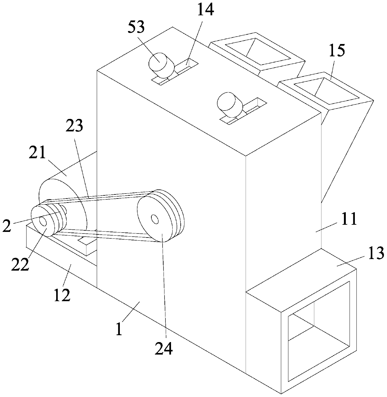
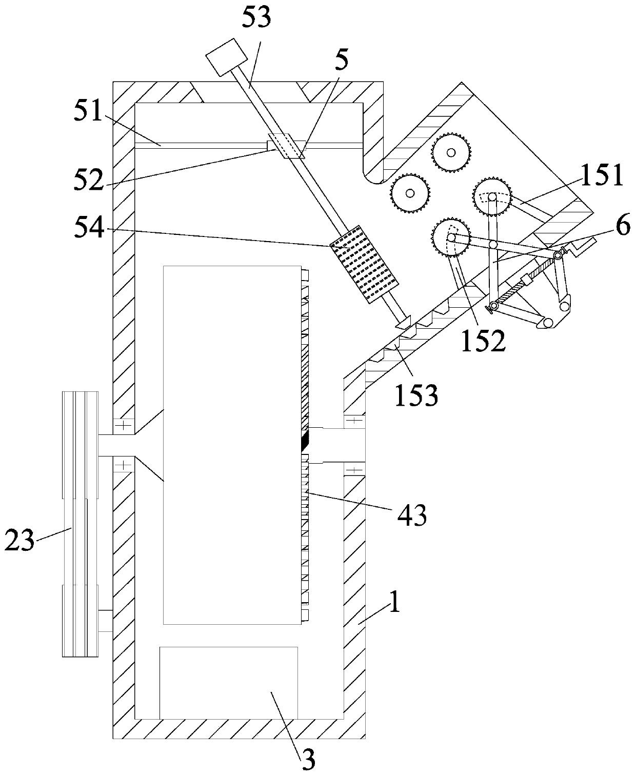
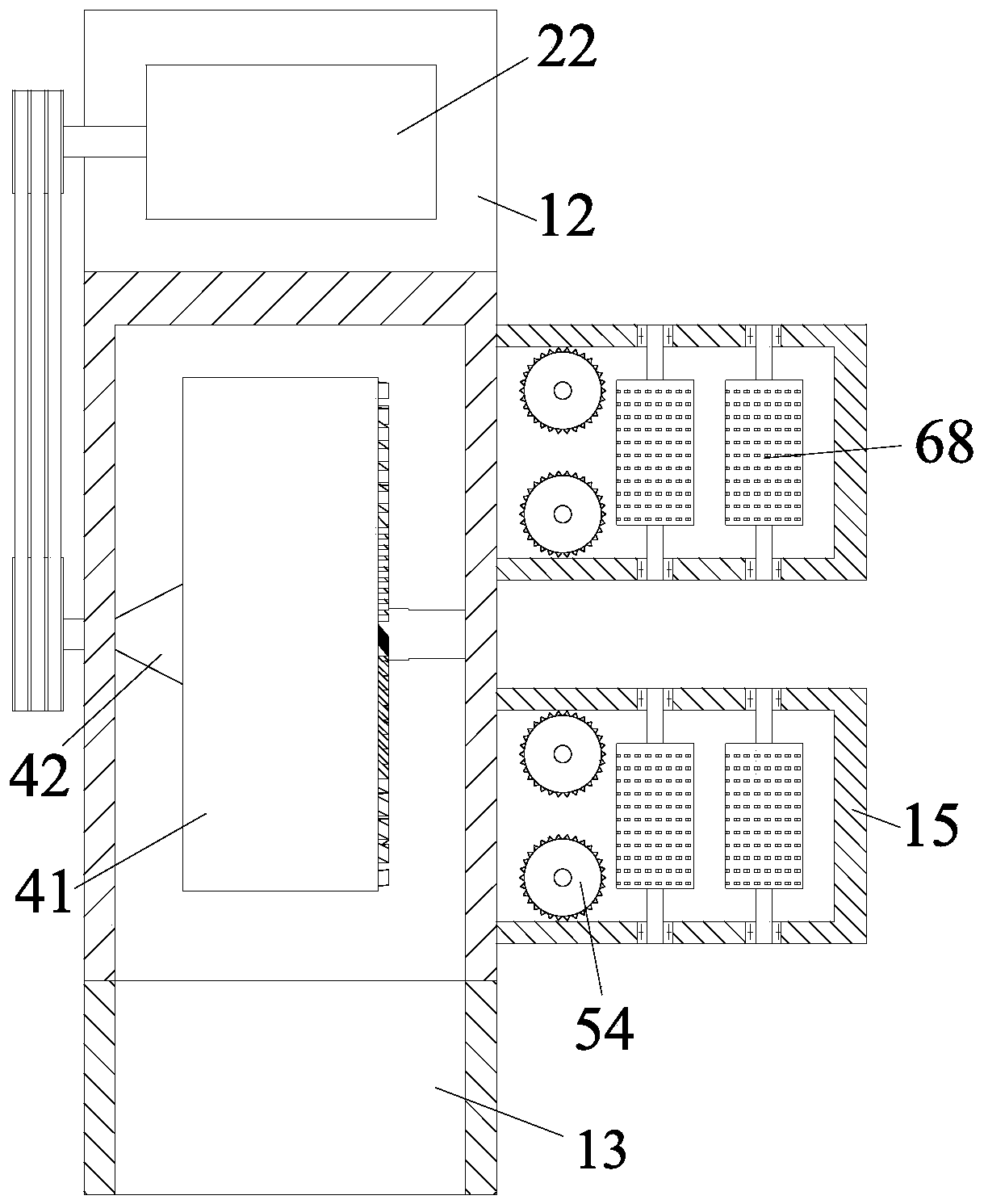
[0035] In order to make the technical means, creative features, objectives and effects of the present invention easy to understand, the following is combined Figure 1 to Figure 8 , To further explain the present invention.
[0036] A shredder for preparing raw material from particle-based wood-based panels, comprising a box body 1, a driving device 2, a blower 3, a shredder device 4, an auxiliary fixing device 5 and a feeding device 6. A driving device 2 is installed on the front side of the box body 1 A blower 3 is installed at the lower end of the box 1, a crushing device 4 is installed in the middle of the box 1, and the crushing device 4 is located at the upper end of the blower 3, an auxiliary fixing device 5 is installed at the upper end of the box 1, and a feeder is installed at the right end of the box 1. 料装置6; Among them:
[0037] The box body 1 includes a housing 11, a motor mounting plate 12, a discharge port 13, a rectangular groove 14 and two feed ports 15. The front side of the housing 11 is welded with a motor mounting plate 12, and the rear side of the housing 11 is equipped with a discharge port. 13. The upper end of the housing 11 is provided with a rectangular groove 14 which functions as a guide and limit. The right end of the housing 11 is installed with a feed port 15 by welding.
[0038] The feed port 15 includes a chute one 151, a chute two 152, and a trapezoidal groove 153. The inside of the feed port 15 is provided with a chute 151 on the front and rear sides, and the inside of the feed port 15 is provided with a chute 152 on both sides. , And the second chute 152 is located at the left end of the first chute 151, and a plurality of trapezoidal grooves 153 are opened at the lower end of the inner part of the feed opening 15, and the trapezoidal grooves 153 are used to assist in fixing the wood during processing.
[0039] The crushing device 4 includes a rotating disk 41, a rotating shaft 42, and a cutting tool set 43. The rotating disk 41 is located inside the housing 11. A rotating shaft 42 is installed in the middle of the rotating disk 41. The rotating shaft 42 is installed in the middle of the housing 11 through a bearing. A cutting tool group 43 is installed on the right end of the disk 41 through a threaded connection. The cutting tool group 43 is evenly arranged along the circumference of the rotating disk 41. During specific work, the driving device 2 drives the rotating shaft 42 to rotate, and the rotating disk 41 rotates synchronously, thereby driving cutting. The cutter group 43 rotates to process the wood material that is transported to the crushing device 4 from the feed port 15.
[0040] The auxiliary fixing device 5 includes two guide rods 51, a guide adjusting sleeve 52, an adjusting rod 53 and two vertical feeding rollers 54. The upper part of the housing 11 is symmetrically welded with a guide rod 51 forward and backward, and the guide rod 51 adopts a sliding fit. A guide adjustment sleeve 52 is installed. The guide adjustment sleeve 52 is equipped with an adjustment rod 53 through a threaded fit. The middle of the adjustment rod 53 is symmetrically installed with a vertical feeding roller 54 through a bearing. The guide rod acts as a guide limit. At this time, the adjusting rod 53 is manually rotated to separate the adjusting rod 53 and the guide adjusting sleeve 52 at the threaded connection. At this time, the adjusting rod 53 drives the guide adjusting sleeve 52 to slide on the guide rod 51 to adjust the vertical feeding The position of the feed roller 54 enables the vertical feed roller 54 to clamp the wood during processing.
[0041] The feeding device 6 includes a fixed plate 61, a connecting rod 62, a connecting rod 63, a connecting rod 64, a connecting rod 65, a rotating column 66, a rotating column 67, a movable feeding roller 68, and a movable feeding Roller two 69, two transverse feeding rollers 6a and rocker arm 6b, the lower end of the feed port 15 is welded with a fixed plate 61, the left side of the fixed plate 61 is connected with a connecting rod 62 through a pin, and the right side of the fixed plate 61 is through a pin The shaft is connected with connecting rod two 63, the upper end of connecting rod 62 is connected with rotating column one 66 through a bearing, rotating column one 66 is connected with connecting rod three 64 through a bearing, and the upper end of connecting rod two 63 is connected with rotating column two 67 through a bearing. Column two 67 is connected with connecting rod four 65 through a bearing. The middle part of connecting rod three 64 and the middle part of connecting rod four 65 are connected by a pin. The upper end of connecting rod three 64 is equipped with a movable feeding roller 68 through a bearing, and the movable feeding roller one The front and rear ends of 68 are located in chute one 151, the upper end of connecting rod four 65 is equipped with movable feeding roller two 69 through bearings, and the front and rear ends of the movable feeding roller 69 are located in chute two 152, and the upper end of the feed port 15 passes The bearing is equipped with a transverse feeding roller 6a. The transverse feeding roller 6a is located above the movable feeding roller 68 and the movable feeding roller 69. The rotating column 66 and the rotating column two 67 are connected by a rocker 6b. The specific work When the distance between the lateral feeding roller 6a and the movable feeding roller 68 and the movable feeding roller 69 is reduced, the rocker arm 6b is manually rotated to make the rotating column 66 and the rotating column two 67 move towards each other, thereby driving the connecting The rod three 64 and the connecting rod four 65 rise, so that the movable feeding roller one 68 rises along the chute one 151, and the movable feeding roller two 69 rises along the chute two 152, thereby reducing the transverse feeding roller 6a and the movable feeding roller one. 68. The distance between the second movable feeding roller 69. When the distance between the horizontal feeding roller 6a, the first movable feeding roller 68 and the second movable feeding roller 69 is enlarged, the rocker arm 6b is rotated in the opposite direction to enlarge the distance .
[0042] The driving device 2 includes a motor 21, a small pulley 22, a transmission belt 23, and a large pulley 24. The upper end of the motor mounting plate 12 is equipped with a motor 21 through a motor mounting seat. The output shaft of the motor 21 is connected to the small pulley 22. The pulley 22 is connected to the large pulley 24 through a transmission belt 23, the large pulley 24 is installed on the left side of the crushing device 4, and the small pulley 22 and the large pulley 24 are both located on the left outside of the housing 11.
[0043] The small pulley 22 and the large pulley 24 have a larger radius difference.
[0044] In specific work, the motor 21 drives the small pulley 22 to rotate, so that the transmission belt 23 rotates, thereby driving the large pulley 24 to rotate. At this time, the rotating shaft 42 connected to the large pulley 24 rotates synchronously, thereby causing the cutting tool group 43 to rotate For wood processing, the difference in radius between the small pulley 22 and the large pulley 24 can reduce the motor speed, thereby reducing the possibility of damage to the cutting tool set 43 and increasing the torque, making the cutting tool set 43 easier to cut the wood.
[0045] The cutting tool group 43 is composed of several cutting tools. The bottom end of the cutting tool is a threaded column, which is screwed into the rotating disk 41. The cutting tool group 43 is evenly arranged along the circumference of the rotating disk 41, and the threaded column at the bottom of the cutting tool When the rotating disk 41 is screwed into, the direction of the cutting tool's edge is different, and the length and thickness of the cut wood chips are different.
[0046] The guide adjustment sleeve 52 includes an adjustment sleeve 521, two guide sleeves 522 and a short shaft 523. The adjustment sleeve 521 is provided with guide sleeves 522 symmetrically on both front and rear sides. The adjustment sleeve 521 and the guide sleeve 522 are welded by the short shaft 523. A thread is provided inside the sleeve 521.
[0047] The upper end of the adjusting rod 53 passes through the rectangular slot 14 and is located outside the housing 11, the middle of the adjusting rod 53 is provided with a thread, the lower end of the adjusting rod 53 is provided with a trapezoidal block, and the trapezoidal block and the trapezoidal groove 153 can be embedded and fitted.
[0048] During specific work, the guide sleeve 522 is sleeved on the guide rod 51 to play the role of limiting and guiding. The adjusting rod 53 is manually rotated, so that the adjusting rod 53 is separated from the adjusting sleeve 521 by the thread in the middle part, thereby Disengage the trapezoidal block from the trapezoidal groove 153. At this time, the guide sleeve 522 can slide left and right on the guide rod 51 to determine the position of the vertical feeding roller 54. Re-tighten the adjusting rod 53 and the adjusting sleeve 521 so that the trapezoidal block is embedded In the trapezoidal groove 153, the vertical feeding roller 54 is used to clamp the wood limit tightly.
[0049] The vertical feeding roller 54, the movable feeding roller 68, the movable feeding roller 69, and the transverse feeding roller 6a are roller columns of the same size and structure. The surface of the transverse feeding roller 6a is provided with a triangle The protrusions are embedded into the surface of the wood through the triangular protrusions, so that the wood is clamped by a limit, thereby reducing the shaking of the wood during processing.
[0050] The first rotating column 66 and the second rotating column 67 are columns with the same size and structure. The center of the rotating column 66 is provided with a threaded hole, and the rocker arm 6b is provided with two sections of threads, and the two sections of threads are in opposite directions , The rocker arm 6b is installed between the rotating column one 66 and the rotating column two 67 by screwing. When the rocker arm 6b is manually rotated, the two ends of the rocker arm 6b have opposite threads, so that the rotating column one 66 and the rotating column two 67 Move in the opposite or opposite direction along the thread to adjust the position between the movable feeding roller 68, the movable feeding roller 69 and the transverse feeding roller 6a.
[0051] in working:
[0052] S1. Spacing adjustment: according to the diameter of the wood, manually rotate the rocker arm 6b to drive the rotating column one 66 and the rotating column two 67 to move toward or against each other, so that the movable feeding roller 68 and the movable feeding roller 69 are sliding Lift in the groove to determine the distance between the movable feeding roller 68, the movable feeding roller 69 and the transverse feeding roller 6a;
[0053] S2. Adjusting auxiliary fixing device 5: Manually rotate the adjusting rod 53 to make the adjusting rod 53 separate from the adjusting sleeve 521, thereby driving the lower end trapezoidal block of the adjusting rod 53 to escape from the trapezoidal groove 153, select the appropriate trapezoidal groove 153 according to the diameter of the wood, and re-set the adjusting rod 53 is screwed into the adjusting sleeve 521, so that the trapezoidal block is embedded in the trapezoidal groove 153, thereby adjusting the position of the vertical feeding roller 54;
[0054] S3. Feeding: After the adjustment is completed, manually put the wood into the feed inlet 15, and start processing;
[0055] S4. Collection: During the processing, the wood chips are blown out of the discharge port 13 by the blower 3, and a collection frame is set at the discharge port 13 to collect and stack the wood chips.
[0056] The above shows and describes the basic principles, main features and advantages of the present invention. Those skilled in the art should understand that the present invention is not limited by the above-mentioned embodiments. The above-mentioned embodiments and the description in the specification only illustrate the principle of the present invention. Without departing from the spirit and scope of the present invention, the present invention will also There are various changes and improvements, and these changes and improvements fall within the scope of the claimed invention. The scope of protection claimed by the present invention is defined by the appended claims and their equivalents.