Wire retention connector system

a wire retention and connector technology, applied in the direction of securing/insulating coupling contact members, coupling device connections, contact members penetrating/cutting insulation/cable strands, etc., can solve the problems of unfavorable wire retention, loss of electrical connection, and electrical hotness of disconnected wires, so as to prevent unintentional disengagement of wires, reduce the rotation of wires, and facilitate manufacturing

a wire retention and connector technology, applied in the direction of securing/insulating coupling contact members, coupling device connections, contact members penetrating/cutting insulation/cable strands, etc., can solve the problems of unfavorable wire retention, loss of electrical connection, and electrical hotness of disconnected wires, so as to prevent unintentional disengagement of wires, reduce the rotation of wires, and facilitate manufacturing

US7488196B2Active Publication Date: 2009-02-10TYCO ELECTRONICS LOGISTICS AG (CH)

Image

  • Wire retention connector system
  • Wire retention connector system
  • Wire retention connector system

Examples


Embodiment Construction

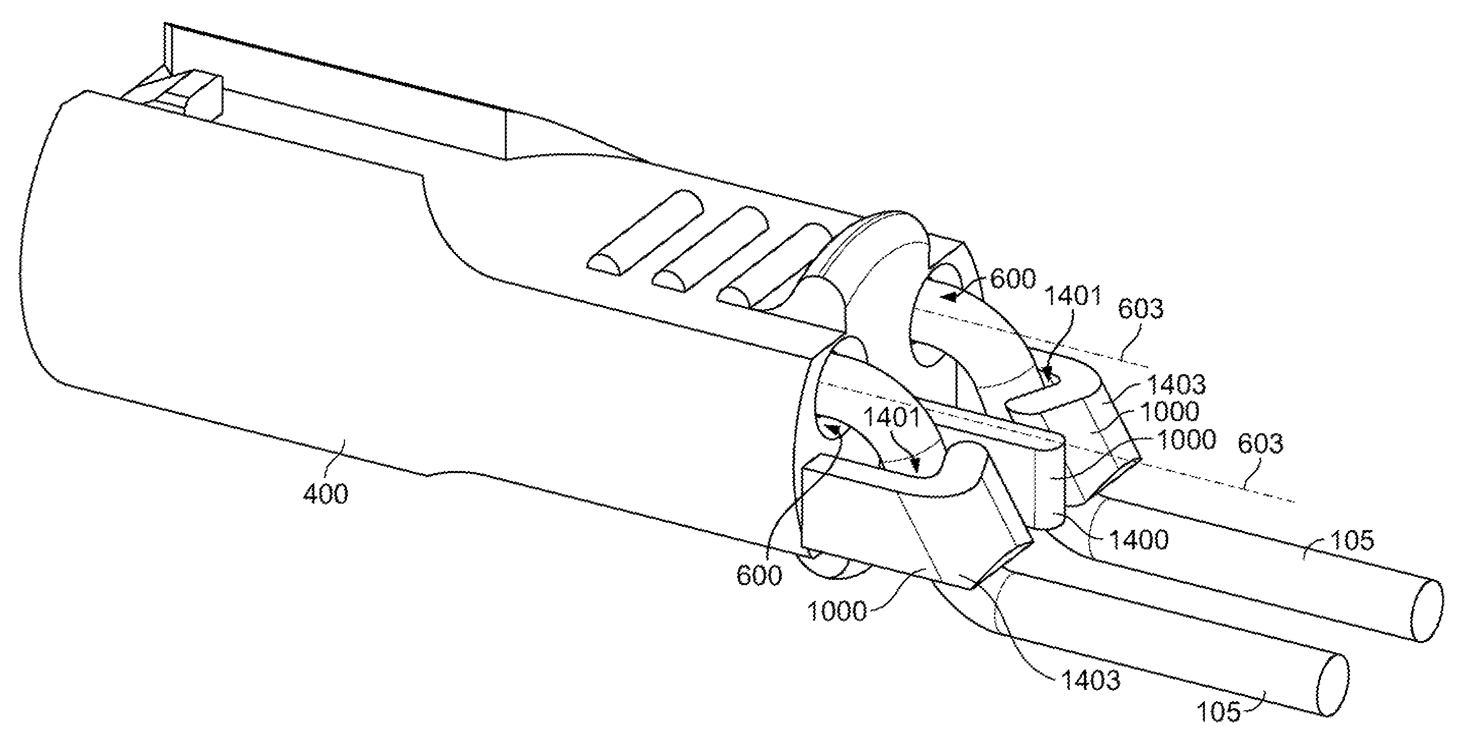
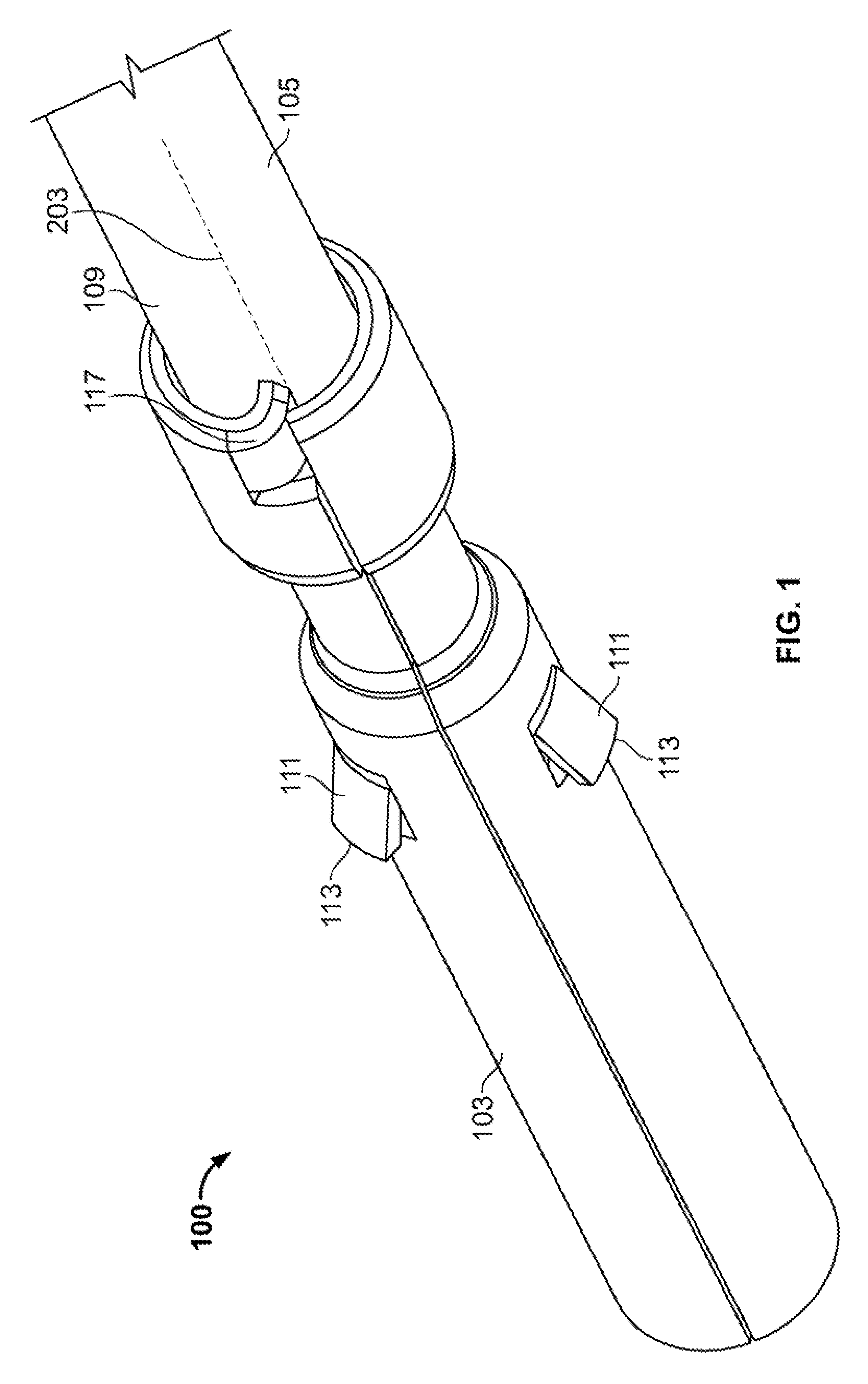
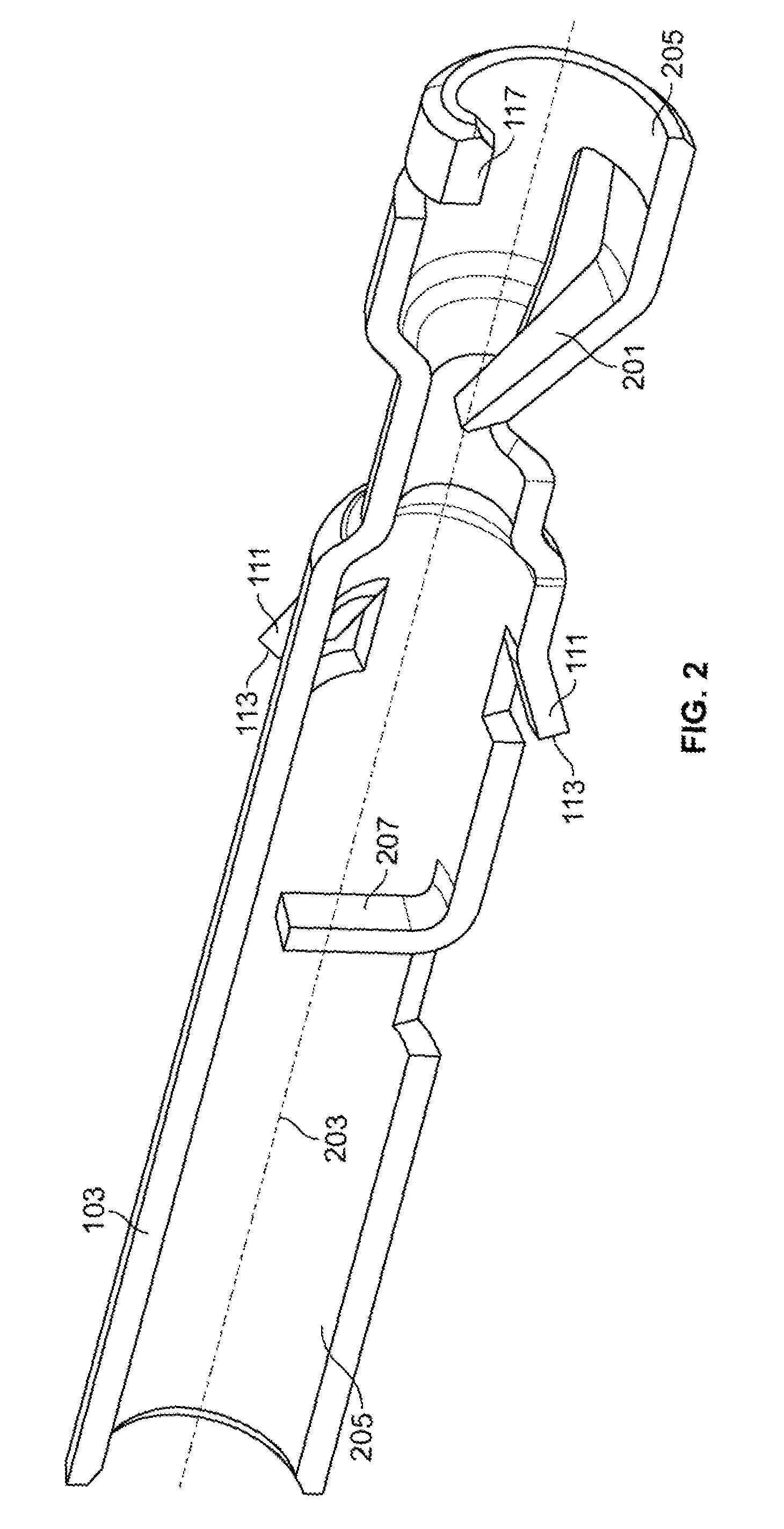
[0052]The present invention includes an embodiment of a wire retaining system for providing resistance against unintentional disengagement of wires inserted therein. In particular, the present invention allows the use of poke-in connections wherein wires may be engaged with the connectors without the use of crimping or special tools. FIGS. 1-4 show an embodiment of a wire retaining system having an wire terminal 100 that is configured to be locked into connector housing 400 (see FIG. 4) and to lockingly receive electrical wire 105. Electrical wire 105 includes conductor 107 and insulation 109. The configuration of wire 105 may be any configuration of wire that includes an insulated conductive portion. Suitable wires 105 include, but are not limited to, 18-gauge solid-core copper wire. Wire terminal 100 includes a terminal body 103, a locking portion or member 111, defining a locking shoulder 113 for engaging a surface of a connector housing 400 (see, e.g., FIG. 4) to securely retain...


PUM


Abstract

A wire retaining connector, connector system and method of connecting wires to connectors to reduce or eliminate unintentional wire disconnection from wire connectors, including disconnection of poke-in connectors. The connectors and connector systems include a connector body having at least one opening configured to receive a wire, the wire including a partially exposed conductor and insulation. The connector body further includes a wire retention member having at least one surface onto which a wire may be engaged. A cutting projection may also be provided on the wire connector to form a channel in the insulation during insertion of the wire into the connector. The wire retention member or the projection provides sufficient retention of the wire to resist disconnection of the wire from the connector body. A method for connecting wires to the connectors is also provided.

Description

FIELD OF THE INVENTION[0001]The present invention is directed to a wire connector, wire connector system and a wire connecting method for providing connection of one or more wires to a connector. In particular, the present invention is directed to a wire connector, wire connector system and a wire connecting method that provides poke-in connections to connectors that substantially resist unintentional disengagement from pulling and / or twisting of the wires.BACKGROUND OF THE INVENTION[0002]Wire terminals are well known in the connector industry. Typically, the terminals include a pin and mating socket, together with a conductor connecting portion. In the event that the terminals are connected to wires, the terminals include a wire connecting section. One such form of wire connecting section is the wire crimp, where the wire is stripped and placed in a terminal end, and then crimped in place where the metal deforms about the conductor to form the electrical connection.[0003]It is desi...

Claims


Application Information

Patent Timeline
10 Feb 2009
Publication
US7488196B2
IPC
H01R13/58
CPC
H01R4/26; H01R13/5833; H01R13/41; H01R13/422; H01R13/58
Inventors
KOCHER, TIMOTHY LEE; DAILY, CHRISTOPHER GEORGE