
Wire retention connector system

Inactive Publication Date: 2008-05-08
TE CONNECTIVITY CORP
View PDF14 Cites 8 Cited by
  • Summary
  • Abstract
  • Description
  • Claims
  • Application Information

AI Technical Summary

Benefits of technology

[0008]The present invention is directed to a wire retaining system that substantially prevents unintentional disengagement of wires inserted into connectors due to pulling and / or twisting or rotating the wires. In particular, the present invention permits a poke-in connection of insulated wires reducing or eliminating wires unintentionally disengaging from the connector.

Problems solved by technology

Typically, this is in the situation where the wires are stripped on site, and where crimping tools are not readily available.
If the wire is pulled and / or twisted while engaged with the connector, the wire may become disconnected from the connector resulting in a loss of electrical connection.
In addition, the disconnected wire may be electrically hot, particularly during installation or maintenance.
The contact engagement effectively cuts helical threads into the conductor during rotation, resulting in an unscrewing of the conductor from the connector.

Method used


Image

  • Wire retention connector system
  • Wire retention connector system
  • Wire retention connector system

Examples


Embodiment Construction

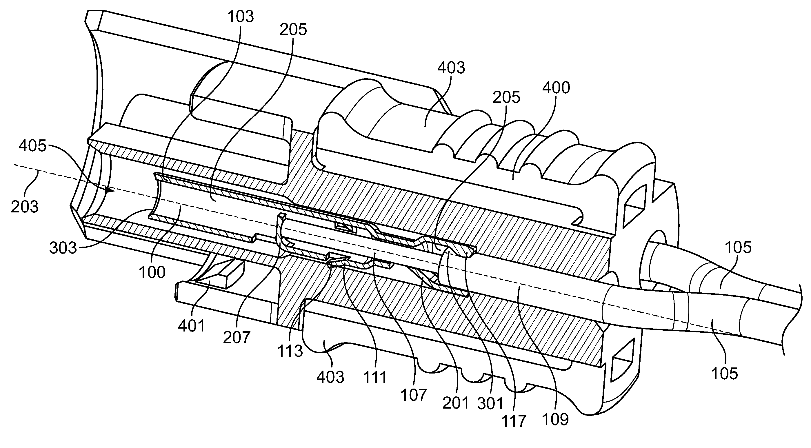
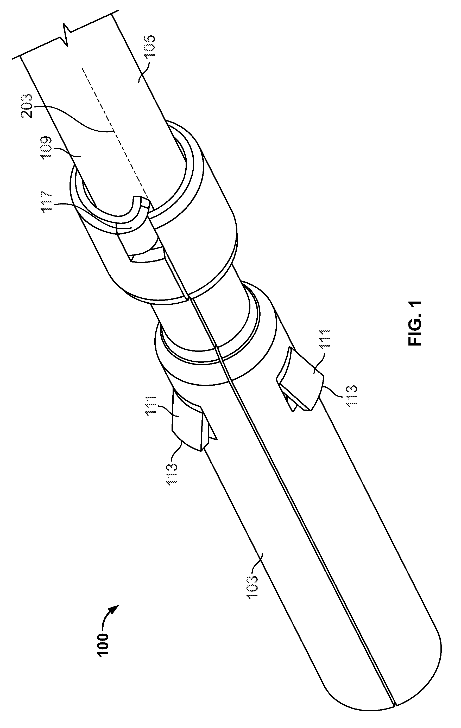
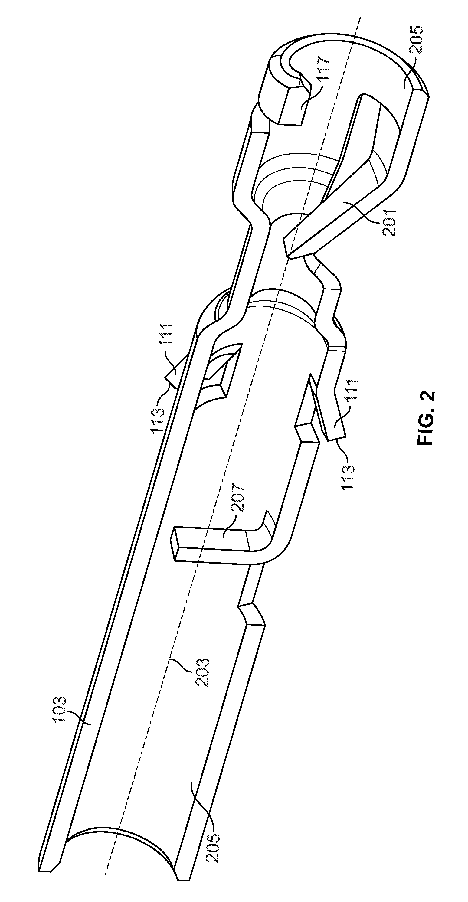
[0064]The present invention includes an embodiment of a wire retaining system for providing resistance against unintentional disengagement of wires inserted therein. In particular, the present invention allows the use of poke-in connections wherein wires may be engaged with the connectors without the use of crimping or special tools. FIGS. 1-4 show an embodiment of a wire retaining system having an wire terminal 100 that is configured to be locked into connector housing 400 (see FIG. 4) and to lockingly receive electrical wire 105. Electrical wire 105 includes conductor 107 and insulation 109. The configuration of wire 105 may be any configuration of wire that includes an insulated conductive portion. Suitable wires 105 include, but are not limited to, 18-gauge solid-core copper wire. Wire terminal 100 includes a terminal body 103, a locking portion or member 111, defining a locking shoulder 113 for engaging a surface of a connector housing 400 (see, e.g., FIG. 4) to securely retain...


PUM


Abstract

A wire retaining connector, connector system and method of connecting wires to connectors to reduce or eliminate unintentional wire disconnection from wire connectors, including disconnection of poke-in connectors. The connectors and connector systems include a connector body having at least one opening configured to receive a wire, the wire including a partially exposed conductor and insulation. The connector body further includes a wire retention member having at least one surface onto which a wire may be engaged. The surface of the wire retention member includes at least one slot or at least one channel. The wire retention member provides sufficient retention of the wire to resist disconnection of the wire from the connector body. A method for connecting wires to the connectors is also provided.

Description

CROSS-REFERENCE TO RELATED APPLICATIONS[0001]This application is a continuation in part of, and claims priority to, U.S. patent application Ser. No. 11 / 555,941 having a filing date of Nov. 2, 2006, and which is hereby incorporated by reference in its entirety.FIELD OF THE INVENTION[0002]The present invention is directed to a wire connector, wire connector system and a wire connecting method for providing connection of one or more wires to a connector. In particular, the present invention is directed to a wire connector, wire connector system and a wire connecting method that provides poke-in connections to connectors that substantially resist unintentional disengagement from pulling and / or twisting of the wires.BACKGROUND OF THE INVENTION[0003]Wire terminals are well known in the connector industry. Typically, the terminals include a pin and mating socket, together with a conductor connecting portion. In the event that the terminals are connected to wires, the terminals include a wi...

Claims


Application Information

Patent Timeline
IPC IPC(8): H01R13/58
CPCH01R4/26H01R4/4818H01R13/5833H01R13/422H01R13/58H01R13/41Y10S439/942Y10S439/948H01R4/48185
Inventor LANDIS, JOHN MICHAELFABIAN, DAVID JAMESDAILY, CHRISTOPHER GEORGEKOCHER, TIMOTHY LEE
Owner TE CONNECTIVITY CORP
Learn More