Rod clip stand

Inactive Publication Date: 2016-06-02
SMITH RUSSELL RICHARD +1
View PDF16 Cites 4 Cited by
  • Summary
  • Abstract
  • Description
  • Claims
  • Application Information

AI Technical Summary

Benefits of technology

[0007]The simple unitary design of the rod clip stand is lightweight and significantly reduces the amount of material compared to that used in conventional rebar support chairs. The rod clip stand can be a plastic molded part arranged in chains of 16 units. These chains can be nested and stacked su

Problems solved by technology

This process of fabricating a rebar grid can be time consuming in that it involves multiple steps, and thus costly from a labor cost standpoint.
In addition, this process of fabric

Method used


Image

  • Rod clip stand
  • Rod clip stand
  • Rod clip stand

Examples


Example

[0019]The following detailed description of the invention is merely exemplary in nature and is not intended to limit the invention or the application and uses of the invention. Furthermore, there is no intention to be bound by any theory presented in the preceding background of the invention or the following detailed description of the invention.

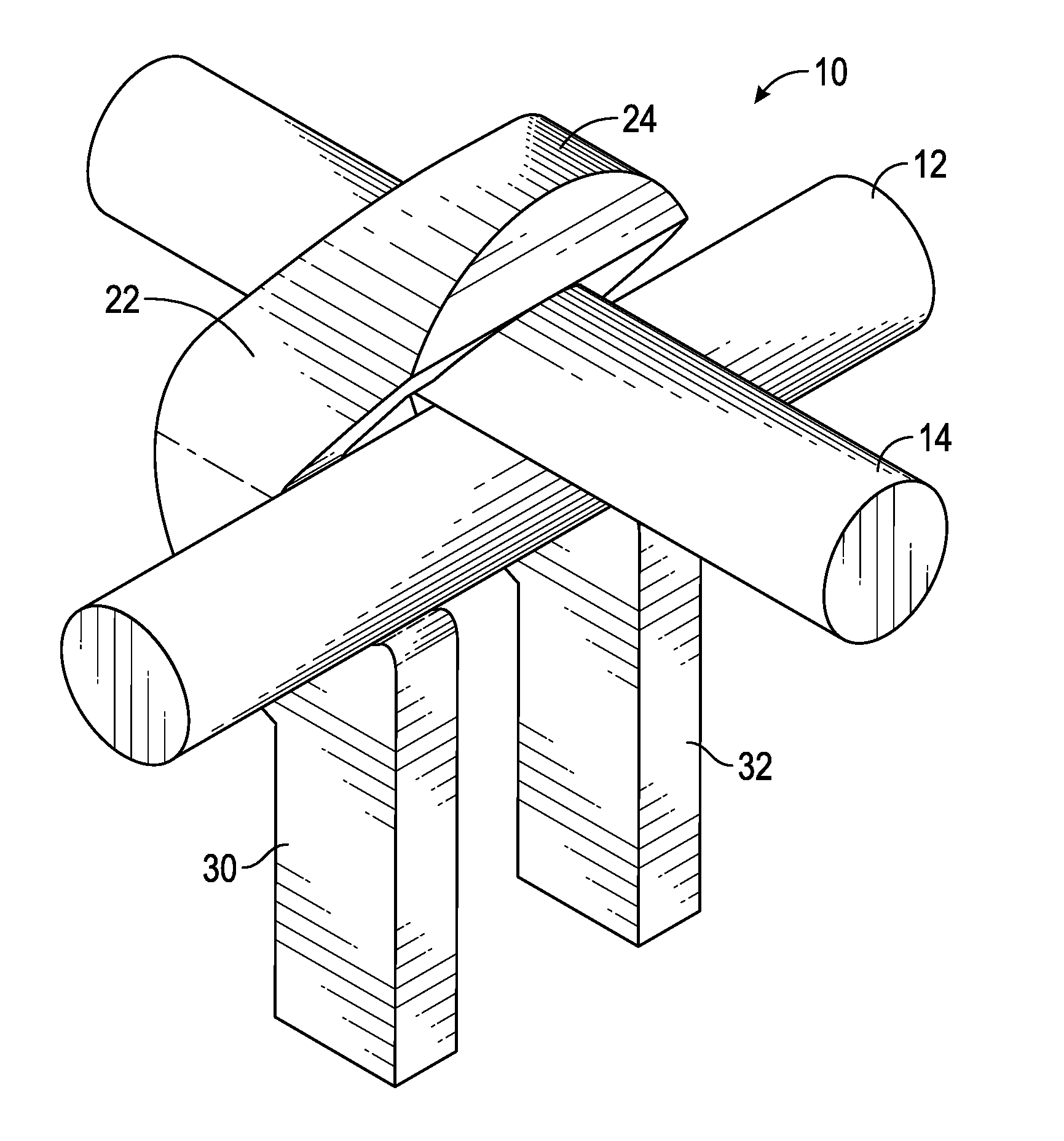
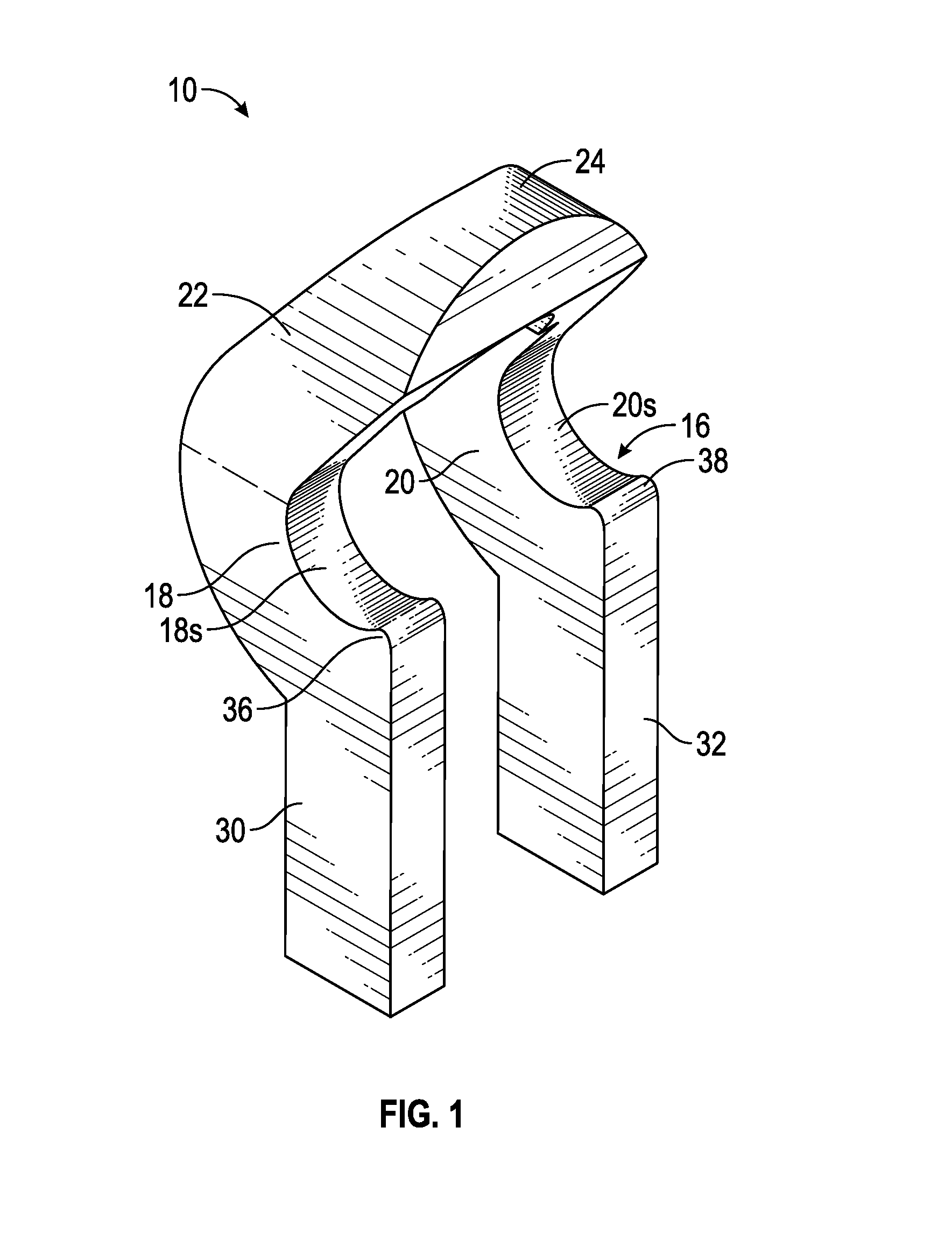
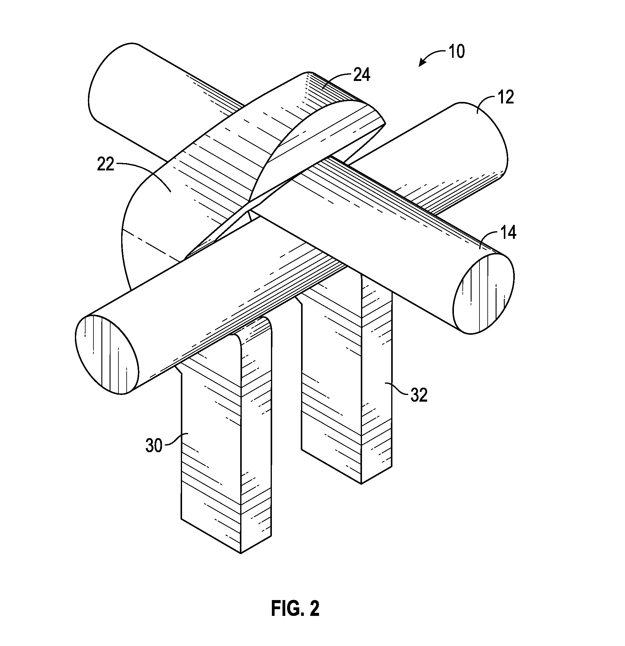
[0020]With reference now FIGS. 1-7, a rod clip stand 10 is illustrated which interconnects and supports a pair of rod elements 12, 14 in a generally orthogonal or perpendicular arrangement. As seen in FIG. 8, a plurality of rod clip stands 10 can be used to assemble a lattice or grid of rod elements 12, 14. In this regard, a rod clip stand 10 couples the rod elements 12, 14 together at each node, or in other words at each point where the rod elements 12, 14 intersect. The rod elements 12, 14 may be reinforcing bars or rebar used to support and strengthen concrete structures. The rod clip stand 10 may have utility in other applications such a...


PUM


Abstract

A rod clip stand is disclosed which is configured to releasably secure and retain a pair of rods in a perpendicular orientation. The rod clip stand has a cradle portion supporting a first rod and an arched portion supporting a second rod. The rod clip stand is particularly well suited for fabricating a rebar grid used to reinforce concrete flatwork.

Description

CROSS-REFERENCES TO RELATED APPLICATIONS[0001]This application claims the benefit of U.S. Provisional Application No. 61 / 957,921, filed Jul. 15, 2013, and U.S. Provisional Application No. 61 / 959,623, filed Aug. 29, 2013. The disclosures of these provisional applications are expressly incorporated by reference herein.FIELD OF THE INVENTION[0002]The present invention generally relates to a means for arranging cylindrical elements in a grid or lattice configuration, and more particularly relates to a rod clip stand configured to releasably secure and retain a pair of rods in a perpendicular orientation, and optionally to locate the rods a distance spaced from an adjacent support surface. The present invention is particularly well suited for fabricating a rebar grid used to reinforce concrete flatwork.BACKGROUND OF THE INVENTION[0003]In certain construction or fabrication applications, it is necessary to assemble a grid or lattice structure from a set of cylindrical element on the job s...

Claims


Application Information

Patent Timeline
IPC IPC(8): E04C5/16
CPCE04C5/167E04C5/163E04C5/168
Inventor SMITH, RUSSELL RICHARDSMITH, DAVID MARVIN
Owner SMITH RUSSELL RICHARD
Why Eureka
Try Eureka