Stepping flexures

a flexural and stepping technology, applied in the field of high-precision micro actuators, can solve the problems of reduced piezoelectric motion, difficulty in clamping piezoelectric/electrostrictive “inchworms” and other problems, and achieve the effect of improving aerodynamics

Inactive Publication Date: 2009-03-17
NASA
View PDF13 Cites 17 Cited by
  • Summary
  • Abstract
  • Description
  • Claims
  • Application Information

AI Technical Summary

Benefits of technology

[0013]According to an aspect of the invention, the actuator architecture can be based on a construct of multiple flat layers, so that actuators built according to plan may be easily constructed, for example, either by MEMS (micro electromechanical systems) techniques or (at the micro level) by shop wire EDM (Electric Discharge Machining) techniques.
[0070]Advantages of embodiments of the present invention over “linear motors” include more force in a more compact package; a simpler construction; more precise steps; holding position with power off; and not requiring bearings, for example.

Problems solved by technology

However, piezoelectric / electrostrictive “inch worms” have difficulties with their clamps, both in reaching their clamp races and in the excessive voltage required to drive these clamps.
They also have problems due to reduced piezoelectric motion at the low temperatures such as are encountered in outer space operations, for example.
Magnetostrictive “inch worms” also have difficulties with their clamps in reaching their races.
Their performance does not degrade in low temperatures but, they are, unacceptably large and bulky due to their coils and mechanical preload structure.
Electromagnetic “inch worms” are also large and bulky, typically do not hold position with power off and have trouble holding with their clamps.
“Inch worms” in general, also typically have difficulties with “glitches” as they grasp and release during steps.
However, piezoelectric / electrostrictive motorized screws have problems associated with poor performance of the piezoelectric / electrostrictive materials in the cold temperatures of outer space operations, for example.
The electromagnetic equivalent of motorized screws has the problem of achieving precise, repeatable very small steps.
Electromagnetic motorized screws also tend to be large due to the windings.
However, voice coils typically do not hold position with power off, and they are relatively large and bulky.
However, linear electromagnetic motors typically do not hold position with power off.
However, these actuators typically do not have sufficient cumulative stroke and are limited in their cold temperature performance.

Method used


Image

  • Stepping flexures
  • Stepping flexures
  • Stepping flexures

Examples


example

From Example in Step Size Calculations above

[0150]θ=8.250022 (E-1) deg. Or 1.439900 (E-2) rad. (Worst Case Situation)[0151]L= 5 / 16 in.[0152]MA=(⅔) [1.999585 / 1.439354 (E-2)]=92.61495

[0153]Note: actuator is limited by Frictional Holding Force. Its' Drive is always stronger than its holding force.

[0154]Holding Force (see, Hayt, William h. Jr., Engineering Electromagnetics, Fourth Edition, Copyright 1981, McGraw-Hill, Inc., ISBN 0-07-027395-2 (p. p. 327 Magnetic Force equation).
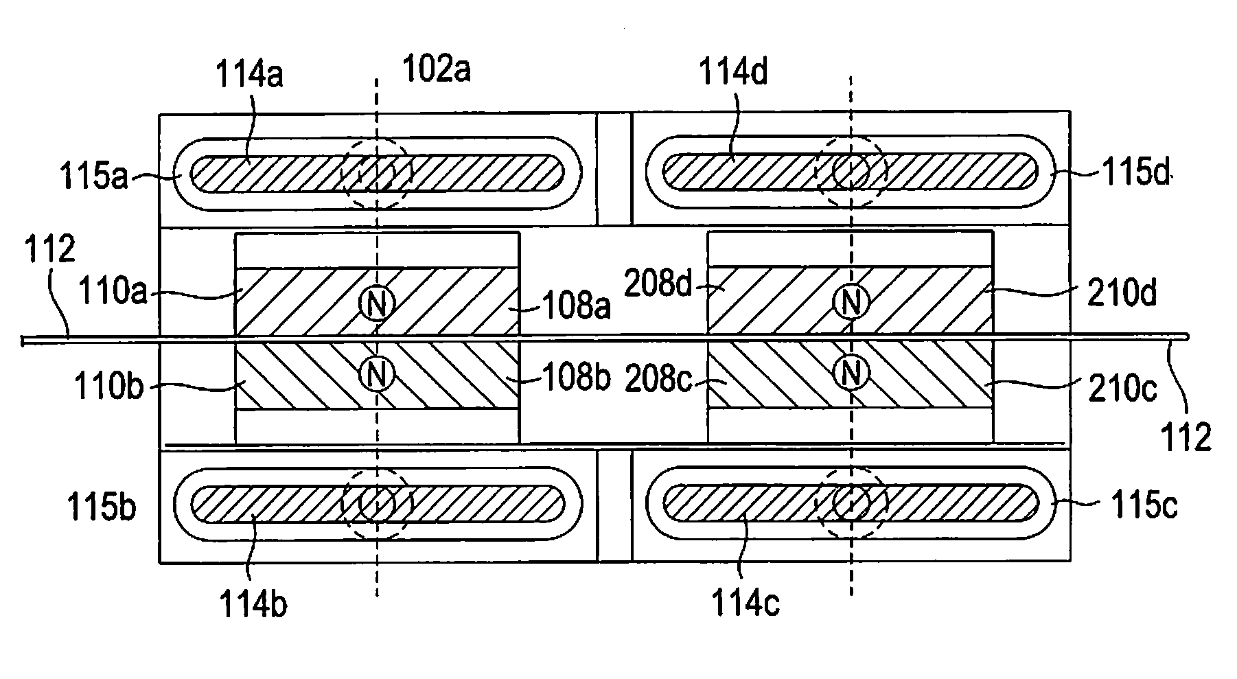
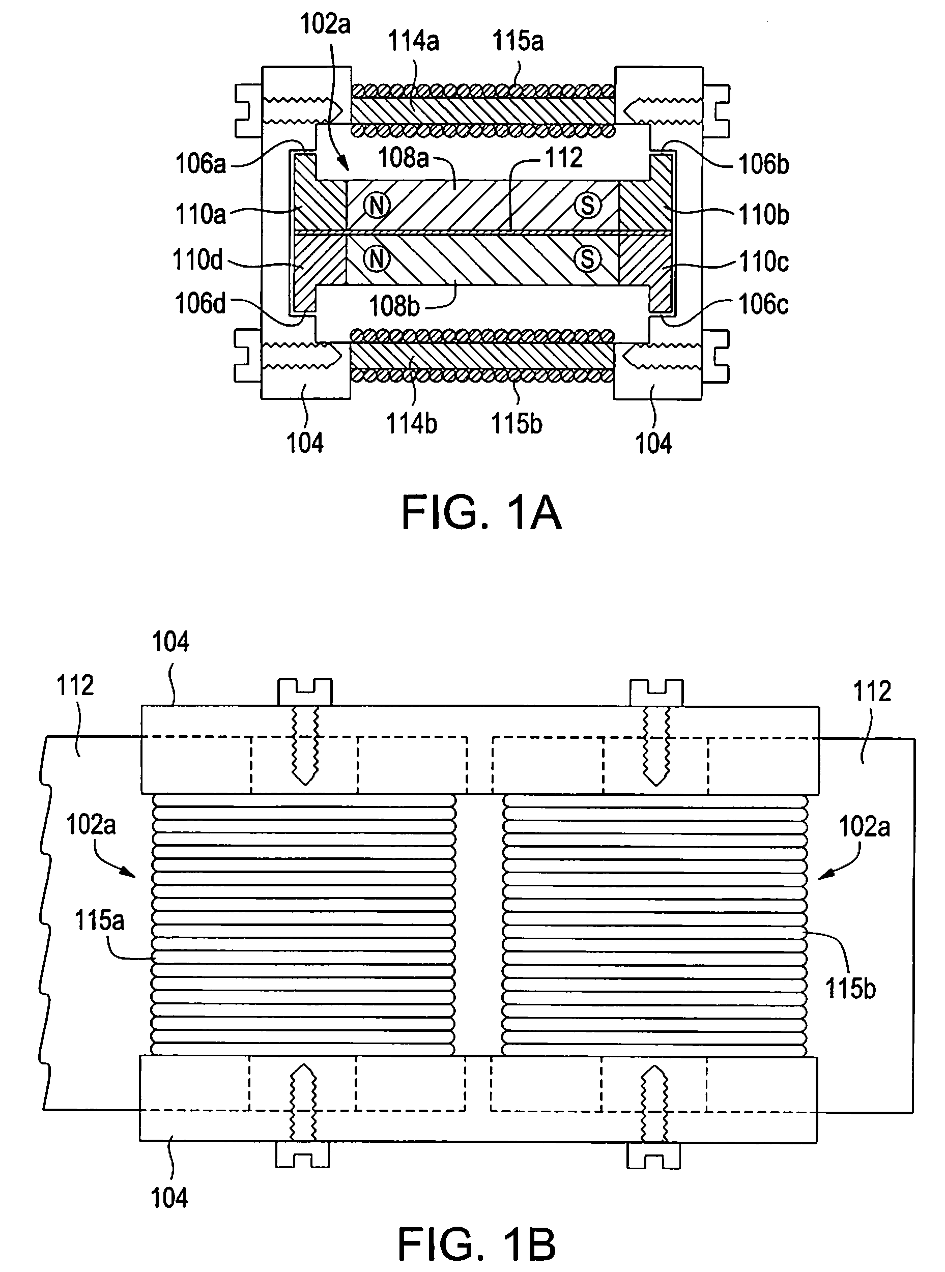
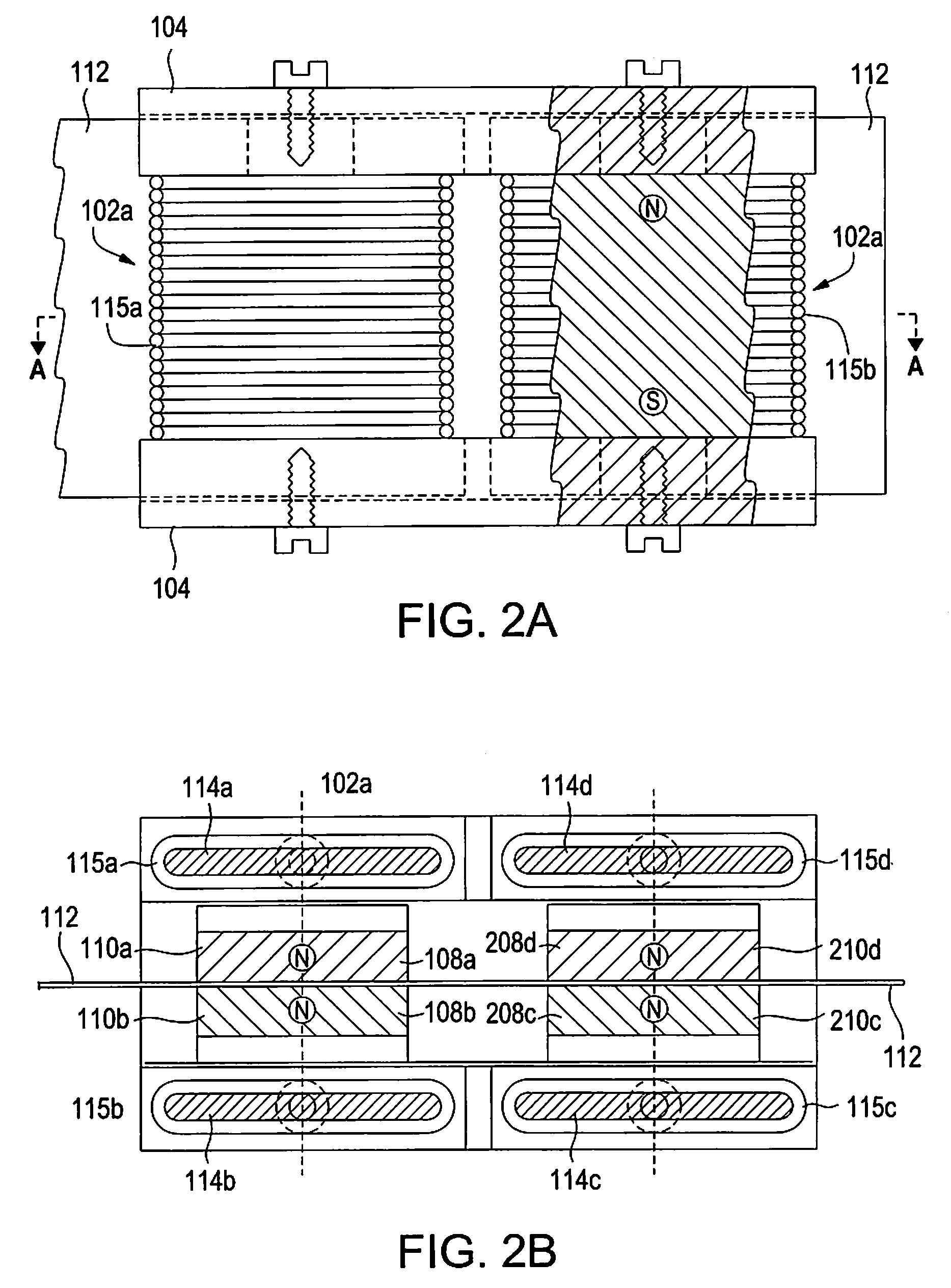
[0155]F=12⁢B2⁢Sμ0;Say⁢⁢B=1⁢⁢Telsa;S=(12⁢⁢in.)×(116⁢⁢in.)×2(3.1)

(Note: Area dimensions in equation 3.1, are taken from FIG. 1 example).

[0156]F=12⁢(12)⁢(12)⁢(116)⁢(2)(4⁢π)⁢(E-7)⁢(40)⁢(40)=2⁢(E⁢⁢7)(64)⁢4⁢π⁡(1600)(3.2)

Resulting in normal forces:

[0157]F=15.54247⁢N=3.491040⁢⁢lbf.(3.3)

Which, in turn, leads to holding (friction) forces:

μS=1; FF=3.491040 lbf.   (3.4)

μS=0.5; FF=1.745520 lbf.

Using high performance magnetic materials (such as Hiperco 50A), B=1.6 Tesla can be used. Using this material in equations (3.1) (3.2)...


PUM

PropertyMeasurementUnit
gap sizeaaaaaaaaaa
lengthaaaaaaaaaa
diameteraaaaaaaaaa

Abstract

An actuator for moving a load has a frame forming a race between two surfaces thereof, at least two elements joined together by at least one flexible member, the elements and the at least one flexible member being disposed between the two surfaces of the frame that forms a race, one of the elements further joined to the load by a portion of the at least one flexible member, wherein when an element comes into contact with a surface of the frame it will stick thereto absent a repelling force, and moving means disposed to selectively attract or repel a corresponding element towards or away from one or the other of the two surfaces of the frame that forms the race. The actuator effects movement of the load in a direction towards or away from the elements, by changing a position of at least one of the elements on a surface of the frame that forms the race.

Description

ORIGIN OF THE INVENTION[0001]The invention described herein was made by an employee of the United States Government, and may be manufactured and used by or for the Government for governmental purposes without the payment of any royalties thereon or therefor.TECHNICAL FIELD[0002]The invention relates to the field of actuators, and in particular to high precision micro actuators.BACKGROUND OF THE INVENTION[0003]Various actuators are known. The term actuator as used herein refers to a device that converts electrical energy into mechanical motion, in particular, for moving a load. For example, so-called “inch worms” are known actuators. Inch worm actuators come in many forms and variations, including piezoelectric, magnetostrictive, electromagnetic, and shaped memory alloy, for example.[0004]However, piezoelectric / electrostrictive “inch worms” have difficulties with their clamps, both in reaching their clamp races and in the excessive voltage required to drive these clamps. They also ha...

Claims


Application Information

Patent Timeline
Patent Type & Authority Patents(United States)
IPC IPC(8): H01F7/02
CPCH01F7/08H01F7/1615H02K15/00H02K57/006H02K1/146H02K1/276H02K99/20
Inventor VRANISH, JOHN M.
Owner NASA
Why Eureka
Try Eureka