Check patentability & draft patents in minutes with Patsnap Eureka AI!

Belt clamp apparatus and method

a belt clamping and belt clamping technology, which is applied in the direction of snap fasteners, buckles, transportation and packaging, etc., can solve the problems of difficult for users of belt clamping belt clamps to locate the clamps at the desired position on the belt, and the belt clamping experience is often very high

Active Publication Date: 2009-06-30
FLEXIBLE STEEL LACING
View PDF2 Cites 4 Cited by
  • Summary
  • Abstract
  • Description
  • Claims
  • Application Information

AI Technical Summary

Benefits of technology

[0007]In accordance with one aspect of the present invention, a belt clamping apparatus is provided that has a housing in which a belt is received. A clamping device has an impact portion adapted to receive an impact force so that a clamping portion of the device is driven into clamping engagement with the belt in the housing. In this manner, a belt clamping operation can be quickly done by application of one or more blows from a mallet, for example, against the impact portion of the clamping device.
[0008]The clamping device preferably includes a distinct actuator member and clamp member with the members configured so that when the actuator member is impacted with an impact force in a direction generally parallel to the belt, the clamp member is cammingly driven in a transverse direction, and preferably generally perpendicular to the belt, into clamping engagement therewith. Alternatively, the clamping device can include only a clamp member that is configured to cooperate with the housing so that when the impact blow is applied thereto in a direction generally parallel to the belt, the clamp member is cammingly driven in a transverse direction into clamping engagement with the belt. In this manner, a separate actuator member is avoided.
[0010]Accordingly, in accordance with a preferred form of the present invention, a belt clamping apparatus is provided that has an actuator and a clamp member that are separate components with the clamp member being driven into clamping engagement with a belt when an impact force is applied to the actuator. As mentioned, for instance several quick blows from a mallet or other impact applying tool against an impact receiving end of the actuator will cause the actuator to drive the clamp member into tight clamping engagement with the belt in a very quick and easy manner. Accordingly, the present belt clamp is much more quickly clamped to the belt than the previously-described clamp that requires a user to turn a pair of tightening screws to advance these screws sufficiently far for driving the clamp member into clamping engagement with the belt.
[0016]In another aspect, the housing includes a body having a generally C-shaped profile with wall portions that vary in thickness in cross-section. The body has a thick, vertical web portion, and a lower shelf portion and an upper roof portion that both extend away from the web portion and which generally have a greater thickness closer to the web portion than further therefrom. The thick web portion and the thick adjacent portions of the shelf and roof portions of the body provide the body with substantially uniform strength particularly along the varying thickness shelf and roof portions thereof while also keeping the weight thereof to a minimum, e.g. less than 5 lbs. with an extruded housing. This is in contrast to the previously-described belt clamp having a U-shaped body that is of substantially constant cross-sectional thickness.
[0017]In a preferred form, the lower shelf portion includes a lip portion that protrudes beyond the upper roof portion away from the web portion for ease in fitting the belt into the internal space.

Problems solved by technology

Because of the tension placed on endless conveyor belts, the belt clamps often experience very high loads.
However, prior to application of the pull force, these belt clamps are not fixed to the belt, and this may make it difficult for users of these belt clamps to locate the clamps at a desired position on the belt.
Further, these types of self-locking belt clamps are more susceptible to slippage along the belt prior to application of a sufficiently high pull force so that the jaws exert a sufficient clamping force to keep the jaws clamped and fixed on the belt.
Slippage of the contoured gripping surfaces of the jaws along the belt can damage the belt and also can present safety concerns as the pull force is being applied to the clamps.
This is a time consuming procedure as both screws need to be turned before the clamping member is driven sufficiently downward to be clamped against the belt.
Further, although the Watkins' belt clamp is prelocked to the belt prior to a belt pulling operation, it does not have self-locking feature such that it has been found that with pull forces of approximately 650 lbs, the belt clamp may slip on the belt.
Also, it can be difficult to insure that the same amount of torque force is applied to each drive screw such that the clamp force applied by the clamp member is substantially uniformly distributed thereacross.

Method used


Image

  • Belt clamp apparatus and method
  • Belt clamp apparatus and method
  • Belt clamp apparatus and method

Examples


Embodiment Construction

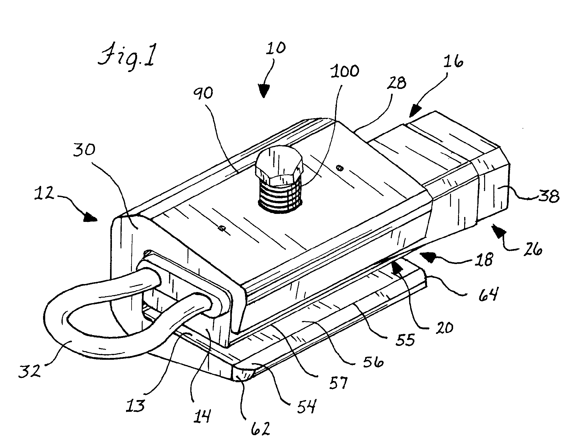
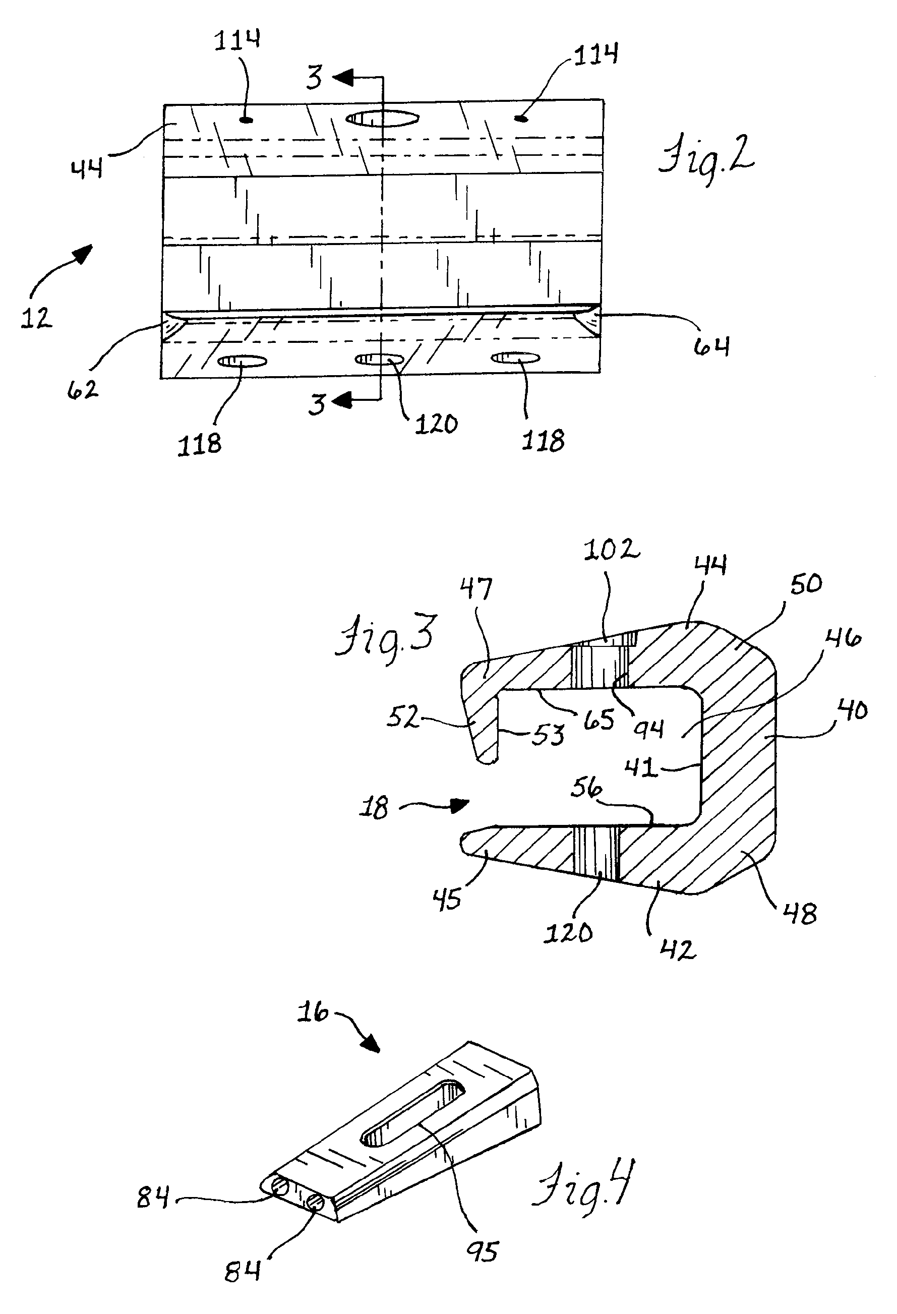
[0041]In FIG. 1, a belt clamp apparatus 10 is illustrated which is adapted for clamping onto a conveyor belt and for pulling the conveyor belt or holding the clamped belt in place as another end of the belt is pulled toward the held end for belt maintenance operations such as for replacing or servicing a belt splice. The belt clamp apparatus 10 has a housing 12 in which a clamping device 13 is received. In the belt clamp 10, the clamping device 13 includes a clamping member 14 and a separate clamp actuator member 16. Further, the housing 12 has an opening 18 along one side thereof through which an edge of the conveyor belt can be fit for being clamped in the housing 12 by the clamp member 14. For this purpose, the clamp actuator 16 is configured to received an impact as by a blow from a mallet or other impact delivering tool to quickly cause the clamp member 14 to shift into clamping engagement with the belt in the housing 12. In this manner, the present belt clamp apparatus 10 prov...


PUM


Abstract

An apparatus and method are provided for clamping a belt with a quick clamping action. The apparatus and method employ an impact force applied to a clamping device that causes a clamping portion of the clamping device to be driven into clamping engagement with the belt received in a housing for the clamping device. In one form, the clamping device has a clamp actuator that includes an impact receiving end preferably disposed outside the housing and a clamp member in the housing that is driven into clamping engagement with the belt by the actuator. The preferred belt clamp has the actuator and clamp member configured so that during belt pulling operations, the clamp also self-locks onto the belt to increase the clamping force applied thereto. In another aspect, the housing preferably has wall portions of varying thickness to provide increased strength where needed while keeping the weight thereof to a minimum.

Description

FIELD OF THE INVENTION[0001]The present invention relates to an apparatus for clamping a belt and, more particularly, to an apparatus and method for clamping a conveyor belt for a belt pulling operation to allow a belt maintenance operation to be performed thereon.BACKGROUND OF THE INVENTION[0002]Clamping mechanisms for conveyor belts typically either clamp along the side edges of the belt or are cross-belt clamps that clamp the belt across the entire lateral width thereof. With the belt clamped, various types of come-along mechanisms can then be connected to the clamps for pulling the belt to perform various maintenance operations thereon. For instance, a typical use of belt clamps is for changing or repairing a splice in the belt. In this instance, clamps will be used on either side of the splice, with the clamp or clamps on one side of the splice being pulled to draw the belt end toward the other end with the other end also pulled toward the opposite pulled end or simply anchored...

Claims


Application Information

Patent Timeline
Patent Type & Authority Patents(United States)
IPC IPC(8): A44B21/00A44B99/00
CPCB65G15/00F16G3/00Y10S24/35Y10T24/45005Y10T24/45079Y10T24/44043Y10T24/3969Y10T24/44009
Inventor MCKEE, JAMES PATRICK
Owner FLEXIBLE STEEL LACING
Features
  • R&D
  • Intellectual Property
  • Life Sciences
  • Materials
  • Tech Scout
  • Unparalleled Data Quality
  • Higher Quality Content
  • 60% Fewer Hallucinations
Learn More