

Hydraulic working machine
a working machine and hydraulic technology, applied in soil shifting machines/dredgers, mechanical equipment, servomotors, etc., can solve the problems of increasing reducing the amount of pressure oil to be fed, and tendency to develop an operational delay in the operation of the boom, so as to reduce the horse power consumption of the pump, reduce the amount of pressure oil to be fed, and continue the smooth operation of the working element
- Summary
- Abstract
- Description
- Claims
- Application Information
AI Technical Summary
Benefits of technology
Problems solved by technology
Method used
Image

Examples
first embodiment
of the Hydraulic Circuit
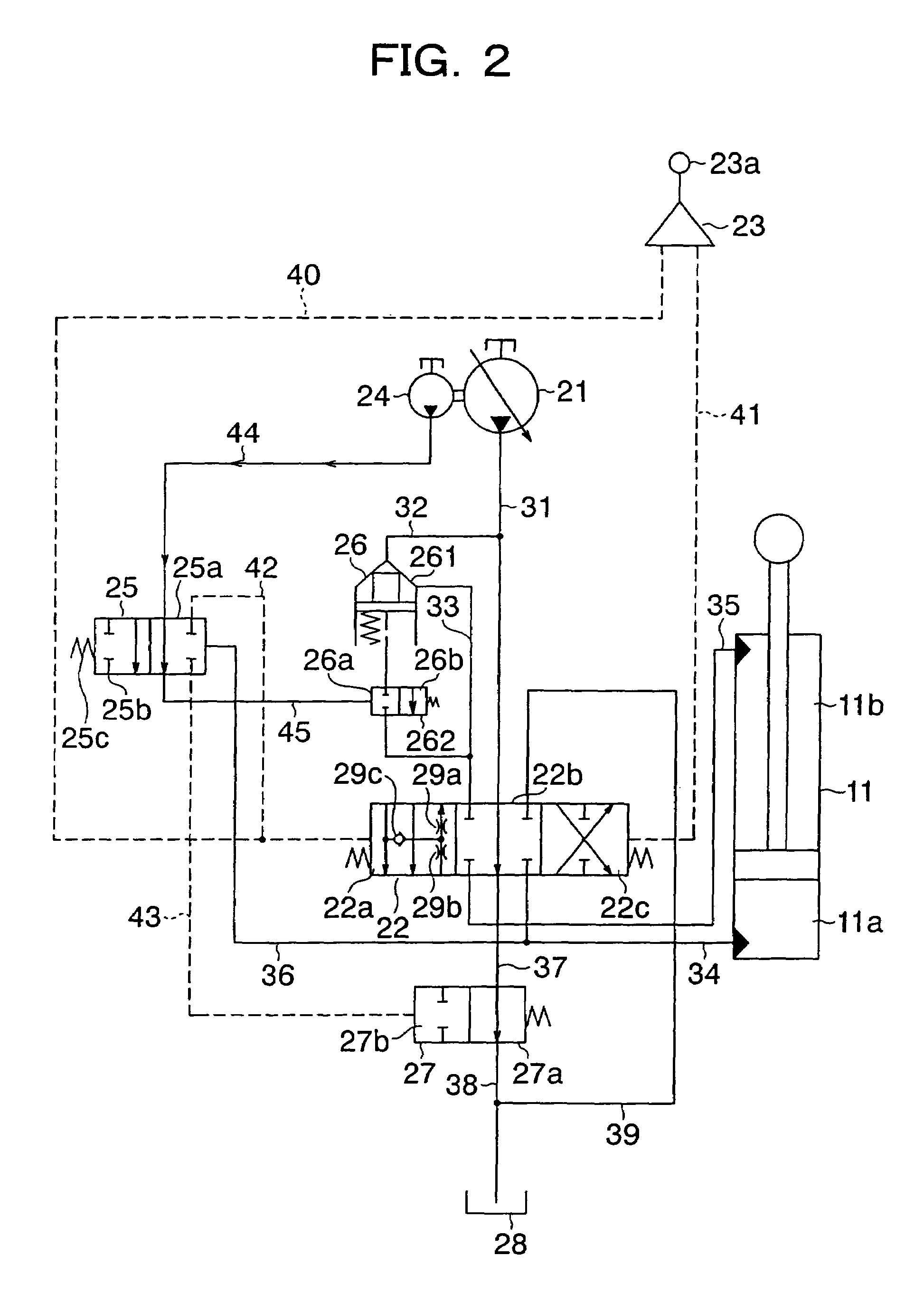
[0054]With reference to FIG. 2 and FIG. 3, a description will next be made of the first embodiment of the hydraulic circuit arranged on the hydraulic working machine. FIG. 2 is a fragmentary circuit diagram of the hydraulic circuit according to the first embodiment, and FIG. 3 is a construction diagram of a control unit. As clearly seen from these figures, the hydraulic circuit according to this embodiment is characterized in that a hydraulically-piloted selector valve is arranged as a jack-up selector valve and oil pressure from one main pump is fed to a hydraulic cylinder.
[0055]As illustrated in FIG. 2, the hydraulic circuit of this embodiment is primarily constructed of a main pump 21, a double-acting, hydraulic boom cylinder 11 arranged for extension or contraction by pressure oil delivered from the main pump 21 to drive the boom 5, a directional control valve 22 for controlling flows of pressure oil to be fed from the main pump 21 to a bottom chamber 11a...
second embodiment
of the Hydraulic Circuit
[0069]With reference to FIG. 4, a description will next be made of the second embodiment of the hydraulic circuit arranged on the hydraulic working machine. FIG. 4 is a circuit diagram of the hydraulic circuit according to the second embodiment, and as clearly seen from this figure, the hydraulic circuit of this embodiment is characterized in that change-over controls of the jack-up selector valve and center bypass selector valve are performed by a solenoid valve.
[0070]In FIG. 4, reference numeral 51 indicates a pressure sensor for sensing a bottom pressure on the hydraulic boom cylinder 11, reference numeral 52 a solenoid valve for changing over the jack-up selector valve 25 and center bypass selector valve 27, reference numeral 53 a controller for receiving an output signal from the pressure sensor 51 and outputting an instruction current value to be fed to a signal input part of the solenoid valve 52, reference numeral 54 a line branching out from the pilo...
third embodiment
of the Hydraulic Circuit
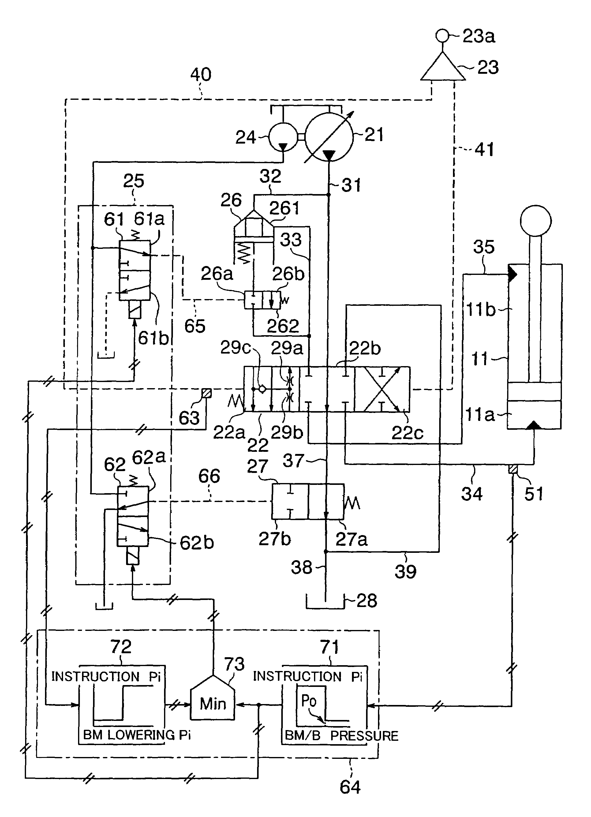
[0075]With reference to FIG. 5, a description will next be made of the third embodiment of the hydraulic circuit arranged on the hydraulic working machine. FIG. 5 is a circuit diagram of the hydraulic circuit according to the third embodiment, and as clearly seen from this figure, the hydraulic circuit of this embodiment is characterized in that two solenoid valves are arranged as a jack-up selector valve, and change-over controls of these two solenoid valves are performed based on the bottom pressure on the hydraulic boom cylinder and the pilot pressure to the directional control valve.
[0076]In FIG. 5, reference numeral 51 indicates a first pressure sensor for sensing a bottom pressure on the hydraulic boom cylinder 11, reference numerals 61, 62 a first and second solenoid valves which make up the jack-up selector valve, reference numeral 63 a second pressure sensor for sensing a pilot pressure in the pilot line 40, reference numeral 64 a controller for rece...
PUM
 Abstract
Description
Claims
Application Information