Lower complexity computation of lattice reduction

a lattice reduction and low-complex technology, applied in the direction of line-faulst/interference reduction, amplitude demodulation, pulse technique, etc., can solve the problems of complex and powerful software tools available, and achieve the effect of simplifying detection

Inactive Publication Date: 2010-02-23
NOKIA CORP
View PDF8 Cites 18 Cited by
  • Summary
  • Abstract
  • Description
  • Claims
  • Application Information

AI Technical Summary

Benefits of technology

[0011]In accordance with another exemplary embodiment of the invention, there is provided a receiver that includes a plurality of receive antenna ports, a channel estimator, a matrix generator, a register, a memory, and a processor. The channel estimator has an input coupled to an output of each of the plurality of receive antenna ports, and an input coupled to the processor and is adapted to determine a channel matrix H for a channel realization. The matrix generator has an input coupled to an output of the channel estimator, and is adapted to determine according to an iterative algorithm a change of basis matrix T that when multiplied with the channel matrix H converges to a matrix H*T that is more orthogonal than the channel matrix H. This simplifies detection. The register is coupled to the matrix generator and is adapted to store an upward bound to the number of iterations the algorithm may perform. The memory is adapted to store the iterative algorithm. The processor terminates further iterations of the algorithm for a current channel realization once the upward bound is reached.

Problems solved by technology

Complex and powerful software tools are available for converting a logic level design into a semiconductor circuit design ready to be etched and formed on a semiconductor substrate.

Method used


Image

  • Lower complexity computation of lattice reduction
  • Lower complexity computation of lattice reduction
  • Lower complexity computation of lattice reduction

Examples


Embodiment Construction

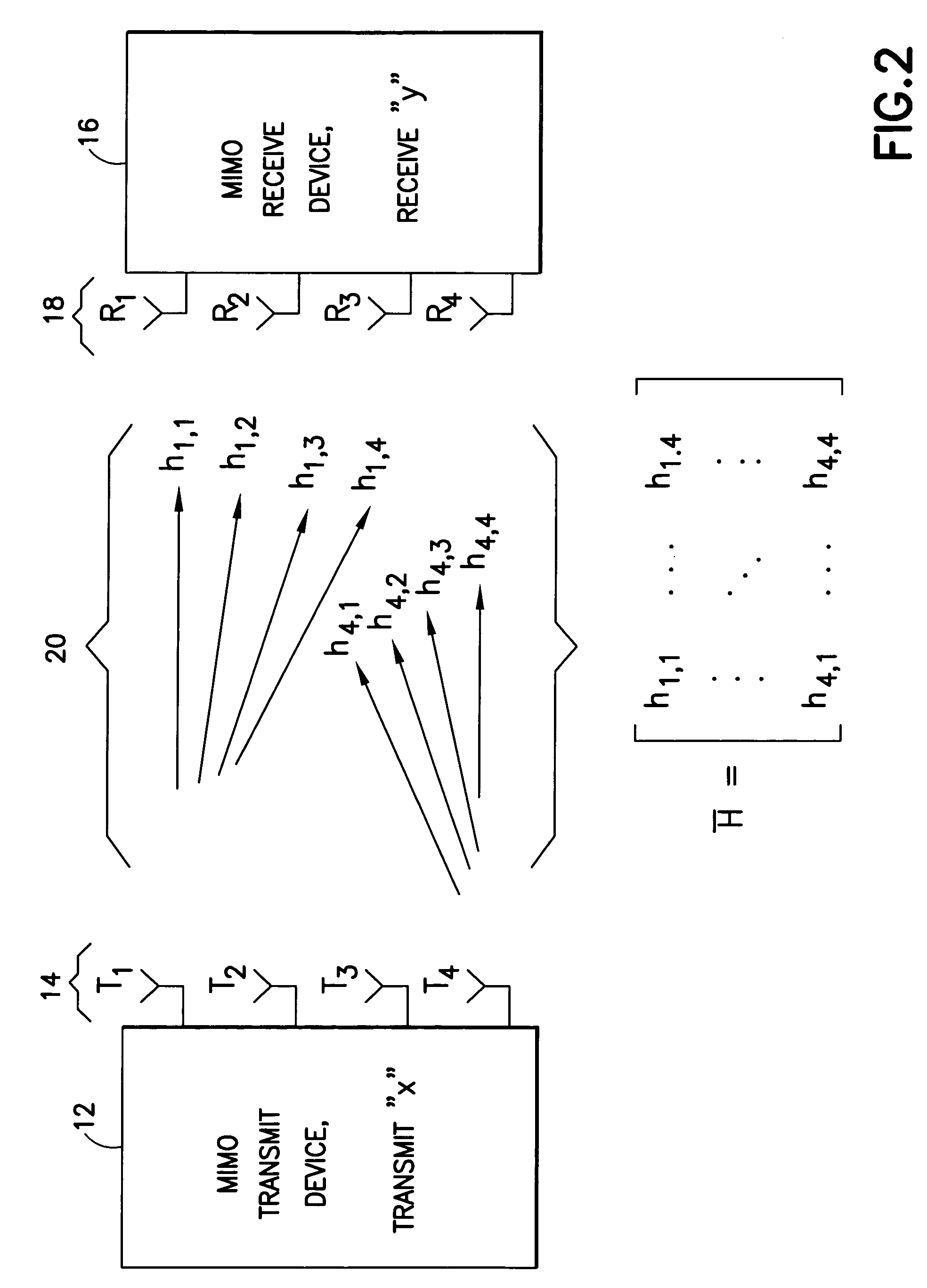
[0023]A generalized MIMO communication system 10 is shown in a simplified schematic form in FIG. 2, where a transmit device 12 such as a base transceiver station of a mobile telephony network transmits a symbol vector x={x0, x1, x2, . . . xi} from each of four transmit antennas 14 (labeled T1 through T4), and a receive device 16 such as a mobile station receives the transmitted symbol vector as y={y0, y1, y2, . . . yi} over the MIMO channel 20. The channel 20 is characterized by the channel matrix H. Each sub-channel from one transmit antenna 14 to one receive antenna 18 is represented as one element ht,r of the channel matrix, with subscripts indicating the path from transmit to receive antenna, so that for the four transmit antennas 14 and four receive antennas 18 illustrated in FIG. 2, the channel matrix is

[0024]H={h11h12h13h14h21h22h23h24h31h32h33h34h41h42h43h44}.

Note that in FIG. 2, only the sub-channels from transmit antennas 1 and 4 are shown, to avoid clutter. Where multipat...


PUM


Abstract

A signal vector is received over a plurality of channels. A channel matrix H is determined that represents at least one of the plurality of channels. An iterative algorithm such as Lenstra-Lenstra-Lovasz is used to determining a change of basis matrix T that when multiplied with the channel matrix H converges to a matrix H*T that is more orthogonal than the channel matrix H. In one aspect the iterative algorithm is upwardly bounded in the number of iterations (e.g., 20 or 30 iterations) that it may perform for any specific channel realization to determine the change of basis matrix T. In another aspect the algorithm is initiated with a matrix derived from a previously determined change of basis matrix. Both aspects may be combined in a single method or device, or either employed separately.

Description

TECHNICAL FIELD[0001]The teachings detailed herein relate to signal detection in a wireless system using a reduced lattice basis to detect the transmitted signal, and is particularly advantageous for detecting transmissions in a multiple-input / multiple output MIMO communication system.BACKGROUND[0002]While MIMO systems offer the possibility of increasing data throughput without increasing bandwidth, the fact that a signal is sent via multiple antennas and / or received at multiple antennas make signal detection computationally complex as compared to systems employing a single transmit and single receive antenna. Specifically, the transmitted signal x is subject to interference and noise while moving through the wireless channel. The received signal y is detected and its value is determined by removing channel influences so as to resolve the best estimate of what the transmitted signal x was. Algebraically, y=Hx+n, where H is the channel matrix and n is noise. Channel influences are de...

Claims


Application Information

Patent Timeline
Patent Type & Authority Patents(United States)
IPC IPC(8): H03D1/06
CPCH04L1/005H04L1/06H04L25/0204
Inventor HEISKALA, JUHA
Owner NOKIA CORP
Why Eureka
Try Eureka