Unlock instant, AI-driven research and patent intelligence for your innovation.

System and method for noise cancellation

a noise cancellation and system technology, applied in the field of noise cancellation, can solve the problems of affecting the sound quality of the ear, the inability to practice, and the inability to reduce the noise of the ear, so as to achieve the effect of reducing noise and low cos

Inactive Publication Date: 2010-04-27
GENERAL ELECTRIC CO
View PDF10 Cites 13 Cited by
  • Summary
  • Abstract
  • Description
  • Claims
  • Application Information

AI Technical Summary

Benefits of technology

[0008]Exemplary embodiments of the invention can provide a low cost, standalone noise reduction system for effectively reducing noise such as the tonal noise of an electric motor or generator.
[0010]Another advantage of exemplary embodiments of the present invention is that predetermined phase angles and amplitudes for the generation of noise canceling acoustic waves can be used, which eliminates the need for sensors and feedback loops. Exemplary embodiments of the invention can thus provide what may be termed “semi-active” noise cancellation.

Problems solved by technology

Electric motors and generators generate a substantial amount of tonal noise during operation.
The noise from the air jets is typically the main source of tonal noise.
Because of its particular frequency and amplitude, the fundamental tonal noise may be especially annoying to human ear perception.
However, this solution is usually expensive and may not always be feasible to practice.
Due to the fact that the motor or generator surface cannot be fully covered, the noise reduction effect is not as good as that from the surrounding walls.
However, the active noise cancellation approach usually involves a complicated setup of input sensors, feedback loop logic, and output acoustic sources.
Thus, active noise cancellation is usually expensive to implement.

Method used


Image

  • System and method for noise cancellation
  • System and method for noise cancellation
  • System and method for noise cancellation

Examples


Embodiment Construction

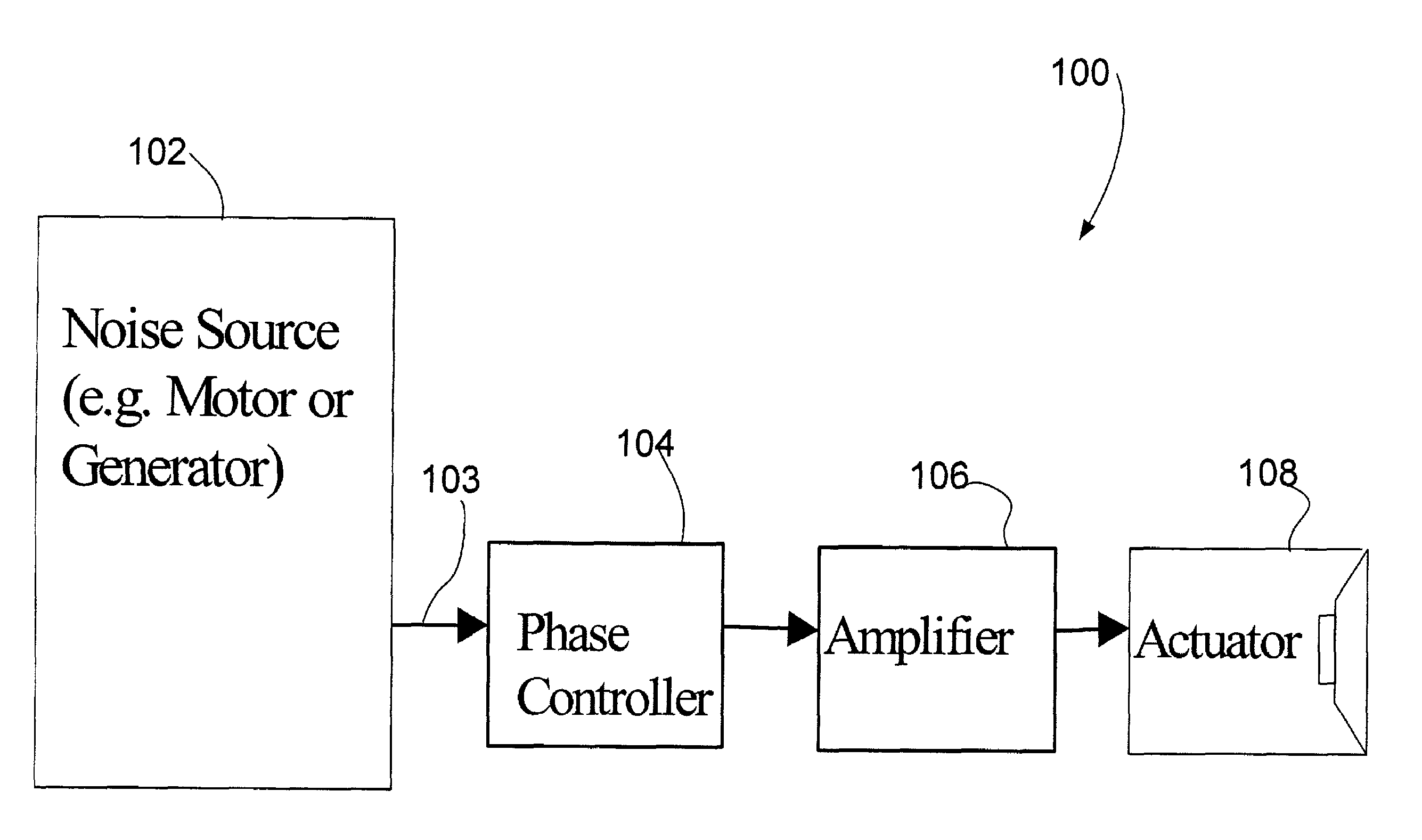
[0018]FIG. 1 is a schematic representation of a semi-active noise cancellation system 100 and its operation, according to an exemplar embodiment of the invention. As shown in FIG. 1, the noise cancellation system 100 comprises a phase controller 104, a signal amplifier 106, and an actuator 108.

[0019]FIG. 1 also shows the noise source 102. By way of example, the noise source 102 may be an electric motor or power generator that is stably operating and producing a repetitive noise. According to a particular example, the noise source 102 may be a two-pole 60 Hz power generator that produces over 20 dB of tonal noise above the broadband noise background during operation. According to another exemplary embodiment of the invention, the noise source 102 may be an aircraft driven by propellers that are rotating at a relatively fixed speed.

[0020]The phase controller 104 is a signal-processing device. According to one embodiment of the invention, the phase controller 104 may receive an input s...


PUM


Abstract

The invention is directed to a system and method for noise cancellation for an apparatus such as an electric motors or generator. The system may comprise a plurality of actuators, a plurality of phase controllers, each phase controller receiving an input signal representing a movement of an apparatus and outputting an output signal based on the input signal and at least one predetermined phase shift, and a plurality of amplifiers, each amplifier receiving an output signal from one of the phase controllers and outputting an amplified signal to drive one of the actuators. The method may comprise the steps of generating a first signal representing a movement of the apparatus, generating at least one second signal based on (a) the first signal, (b) at least one predetermined phase shift, and (c) at least one predetermined amplitude, and driving at least one actuator with the at least one second signal.

Description

BACKGROUND OF THE INVENTION[0001]The present invention relates generally to the field of noise cancellation and more particularly to a system and method for noise cancellation in apparatus such as electric motors and generators.[0002]Electric motors and generators generate a substantial amount of tonal noise during operation. In air-cooled generators, for example, the excitation of the tonal noise comes from two major sources: the electromagnetic force and the rotor jets. The noise from the air jets is typically the main source of tonal noise. The air jets create a tonal noise at a fundamental frequency that equals twice the rotational frequency of the rotor. For example, in a two-pole 60 Hz power generator, the fundamental tonal noise has a frequency of 120 Hz. Because of its particular frequency and amplitude, the fundamental tonal noise may be especially annoying to human ear perception.[0003]To meet customer specifications or regulatory requirements, a number of solutions exist ...

Claims


Application Information

Patent Timeline
IPC IPC(8): A61F11/06G10K11/16H03B29/00G10K11/178
CPCG10K11/1788G10K2210/511G10K2210/3215G10K2210/10G10K11/17823G10K11/17857G10K11/17873
Inventor LUO, HUAGENGBAEHMANN, PEGGY LYNNBARNES, GARY RANDALLNAUMIEC, ROBERT JOHNDAWSON, RICHARD NILS
Owner GENERAL ELECTRIC CO