Laser scanning microscope and microscopic observing method

a scanning microscope and microscopic technology, applied in the field of laser scanning microscope, can solve problems such as taking some time, and achieve the effect of reducing the execution time of photostimulation

Inactive Publication Date: 2010-05-25
OLYMPUS CORP
View PDF14 Cites 39 Cited by
  • Summary
  • Abstract
  • Description
  • Claims
  • Application Information

AI Technical Summary

Benefits of technology

[0008]The present invention provides a laser scanning microscope that can reduce a photostimulation execution time from the start of photostimulation to the end at a photostimulation region.

Problems solved by technology

However, with this conventional laser scanning microscope, the sample is two-dimensionally scanned with the laser beam for stimulation by the galvano mirror for photostimulation and it takes some time from the start of photostimulation to the end.

Method used


Image

  • Laser scanning microscope and microscopic observing method
  • Laser scanning microscope and microscopic observing method
  • Laser scanning microscope and microscopic observing method

Examples


first embodiment

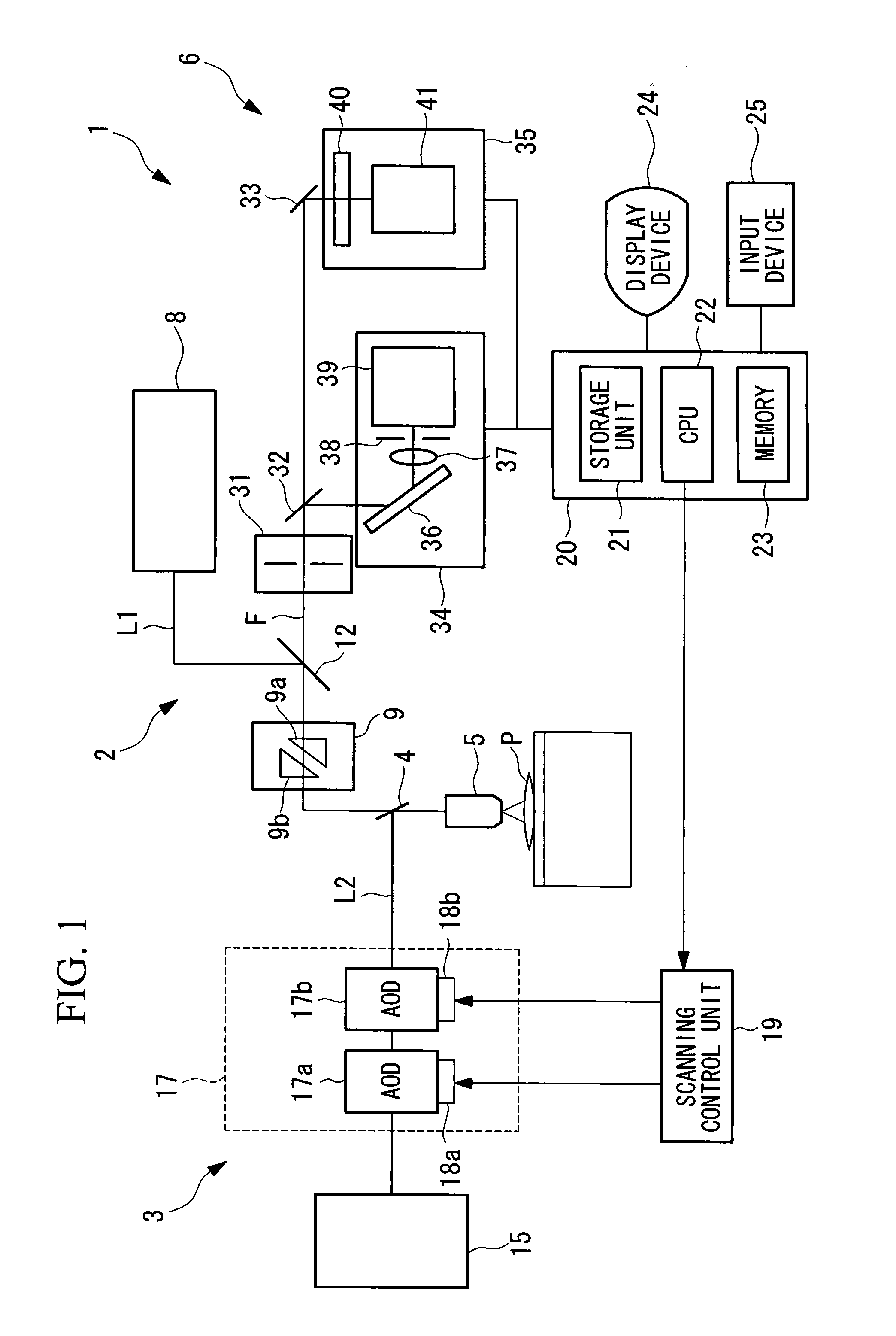
[0060]Referring to FIG. 1, a laser scanning microscope according to the first embodiment is a laser scanning confocal microscope. As shown in FIG. 1, optical parts such as various lenses and a pinhole are omitted for the purpose of a brief description.

[0061]Referring to FIG. 1, a laser scanning microscope 1 according to the first embodiment of the present invention comprises: a scanning optical system 2 for observation that performs scanning with a laser beam L1 for observation; a scanning optical system 3 for stimulation that performs scanning of a laser beam L2 for stimulation; a dichroic mirror 4 that combines waves of the laser beam L1 for observation and the laser beam L2 for stimulation; an objective lens 5 that collects the wave-combined laser beam L1 for observation and the laser beam L2 for stimulation, emits the collected the laser beam L1 for observation and the laser beam L2 for stimulation to a sample P, condenses fluorescent light F generated by exciting a fluorescent ...

second embodiment

[0128]Next, a description will be given of a laser scanning microscope according to the second embodiment of the present invention.

[0129]The laser scanning microscope according to the second embodiment is different from that according to the first embodiment in that the CPU 22 also controls the amplitude of the high-frequency signals applied to the vibrators 18a and 18b.

[0130]Hereinbelow, the common points to those according to the first embodiment with respect to the laser scanning microscope according to the second embodiment will not described, and only different points will be described.

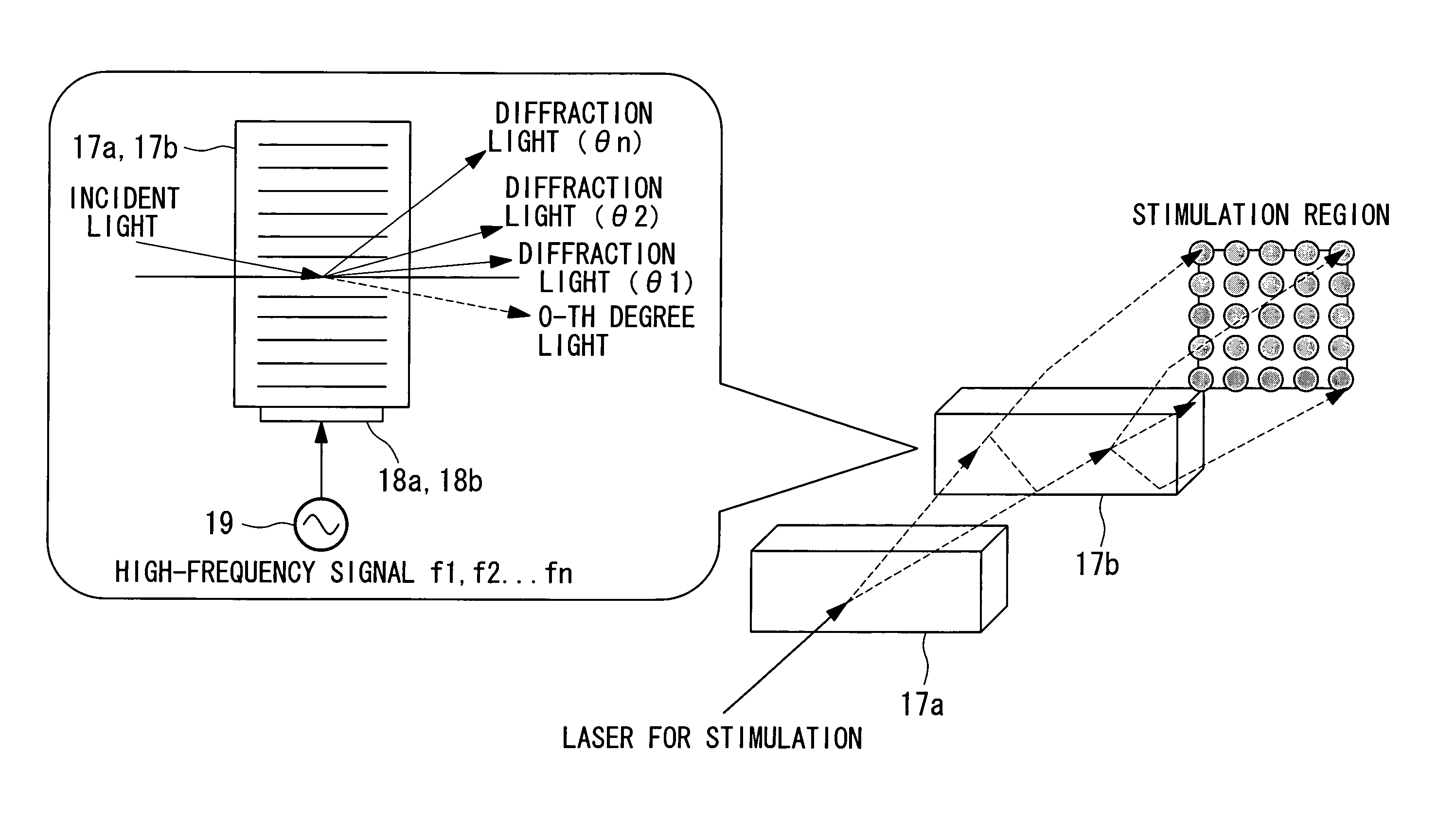
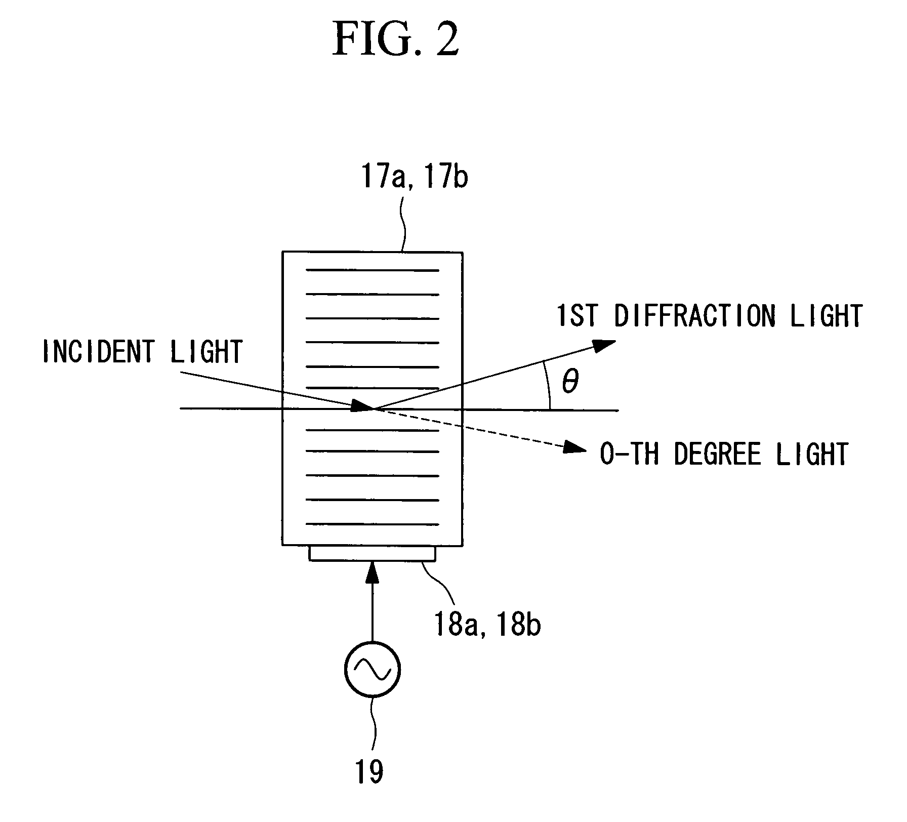
[0131]Referring to FIG. 1, the acoustooptic devices 17a and 17b used for the second scanner 17 have the feature that the intensity of the laser beam L2 for stimulation after the diffraction, i.e., to be emitted is varied depending on the frequency band of the high-frequency signals applied to the vibrators 18a and 18b. Herein, there is a proportional relationship between the intensity of the las...

third embodiment

[0143]Next, a description will be given of a laser scanning microscope according to the third embodiment of the present invention.

[0144]Unlike the laser scanning microscope 1 according to the first embodiment, a laser scanning microscope according to the third embodiment has a galvanic mirror 51 that is mechanically vibrated for light deflection as shown in FIG. 16, in place of the second acoustooptic device 17b.

[0145]The galvanic mirror 51 scans the fluorescent image in the vertical direction with the laser beam L2 for stimulation that position-adjusts the fluorescent image in the horizontal direction with the first acoustooptic device 17a.

[0146]For example, with the laser scanning microscope, the laser beam L2 for stimulation emitted from the laser beam source 15 for stimulation are set as the laser beam L2 for stimulation with the one-dimensional distribution in the horizontal direction by the first acoustooptic device 17a, and are guided to the galvanic mirror 51. The galvanic...


PUM

PropertyMeasurementUnit
laser scanning microscopeaaaaaaaaaa
fluorescent imageaaaaaaaaaa
frequenciesaaaaaaaaaa

Abstract

To provide a laser scanning microscope including a laser beam source for stimulation that emits a laser beam for stimulation for applying photostimulation to a sample, a scanner that performs scanning with the laser beam for stimulation, a control device that controls the scanner, and an objective lens that condenses the laser beam for stimulation used for scanning by the scanner to the sample. The scanner has at least one acoustooptic device arranged on an optical path of the laser beam for stimulation. The control device determines a plurality of frequencies on the basis of the position and the range of a photostimulation region, and simultaneously applies the high-frequency signals of the determined plurality of frequencies to a vibrator attached to the acoustooptic device.

Description

BACKGROUND OF THE INVENTION[0001]1. Field of the Invention[0002]The present invention relates to a laser scanning microscope. In particular, the present invention relates to a laser scanning microscope and a microscopic observing method for scanning a laser beam for stimulation with an acoustooptical effect.[0003]This application is based on Japanese Patent Application No. 2006-148258, the content of which is incorporated herein by reference.[0004]2. Description of Related Art[0005]Conventionally, a laser scanning microscope having a scanning optical system for observation that observes a sample and a scanning optical system for stimulation that applies photostimulation to a sample is well known (e.g., refer to Japanese Unexamined Patent Application Publication No. Hei 10-206742).[0006]With this laser scanning microscope, a laser beam for stimulation emitted from a laser beam source for stimulation is two-dimensionally scanned by a scanner using a galvano mirror, and is emitted to t...

Claims


Application Information

Patent Timeline
Patent Type & Authority Patents(United States)
IPC IPC(8): G02B21/06G02F1/33
CPCG02B21/0048G02B21/0076G02B21/0064
Inventor YAMASHITA, YUSUKEARAYA, AKINORI
Owner OLYMPUS CORP
Why Eureka
Try Eureka