Light bulb with light emitting elements for use in conventional incandescent light bulb sockets

a technology of light emitting elements and light bulbs, which is applied in the field of light bulb apparatuses, can solve problems such as the loss of the entire series circuit, and achieve the effect of reducing or eliminating any additional electrical components

Inactive Publication Date: 2010-06-01
CHEN TAIMING
View PDF14 Cites 154 Cited by
  • Summary
  • Abstract
  • Description
  • Claims
  • Application Information

AI Technical Summary

Benefits of technology

[0013]A series of LEDs are mounted on a plurality of printed circuit boards (PCBs). The LEDs may be in a series or parallel circuit array as desired. A series circuit works well, as the reliability of such LED devices is such that it is unlikely that any will break down, which would result in loss of the entire series circuit. Moreover, a series circuit of LEDs allows the LEDs to act as a series of mutual voltage reduction devices for the other LEDs in the series circuit, thus reducing or eliminating any additional electrical components which might otherwise be required.

Problems solved by technology

A series circuit works well, as the reliability of such LED devices is such that it is unlikely that any will break down, which would result in loss of the entire series circuit.

Method used


Image

  • Light bulb with light emitting elements for use in conventional incandescent light bulb sockets
  • Light bulb with light emitting elements for use in conventional incandescent light bulb sockets
  • Light bulb with light emitting elements for use in conventional incandescent light bulb sockets

Examples


Embodiment Construction

[0028]Prior to proceeding to the more detailed description of the present invention, it should be noted that, for the sake of clarity and understanding, identical components which have identical functions have been identified with identical reference numerals throughout the several views illustrated in the drawing figures.

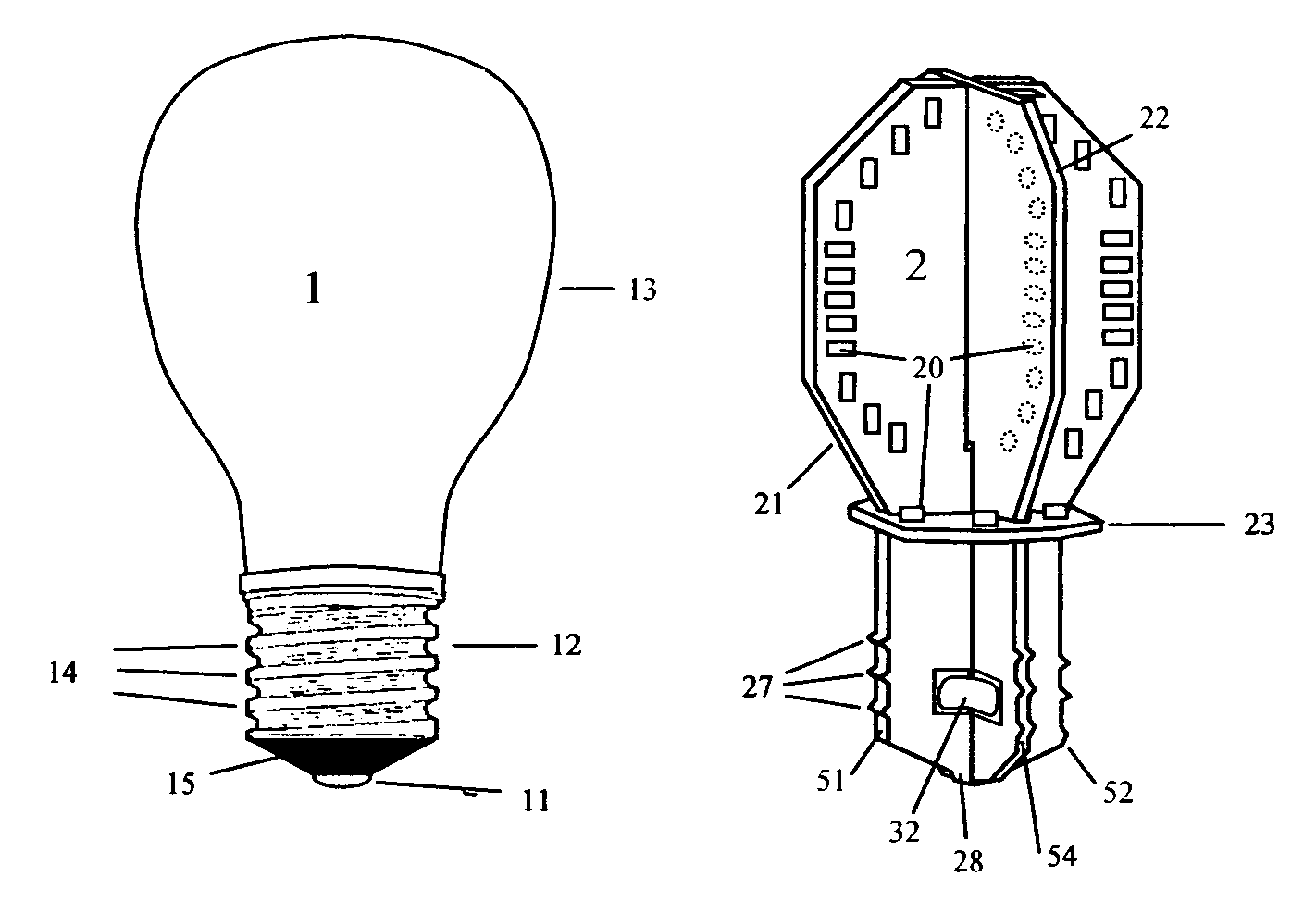
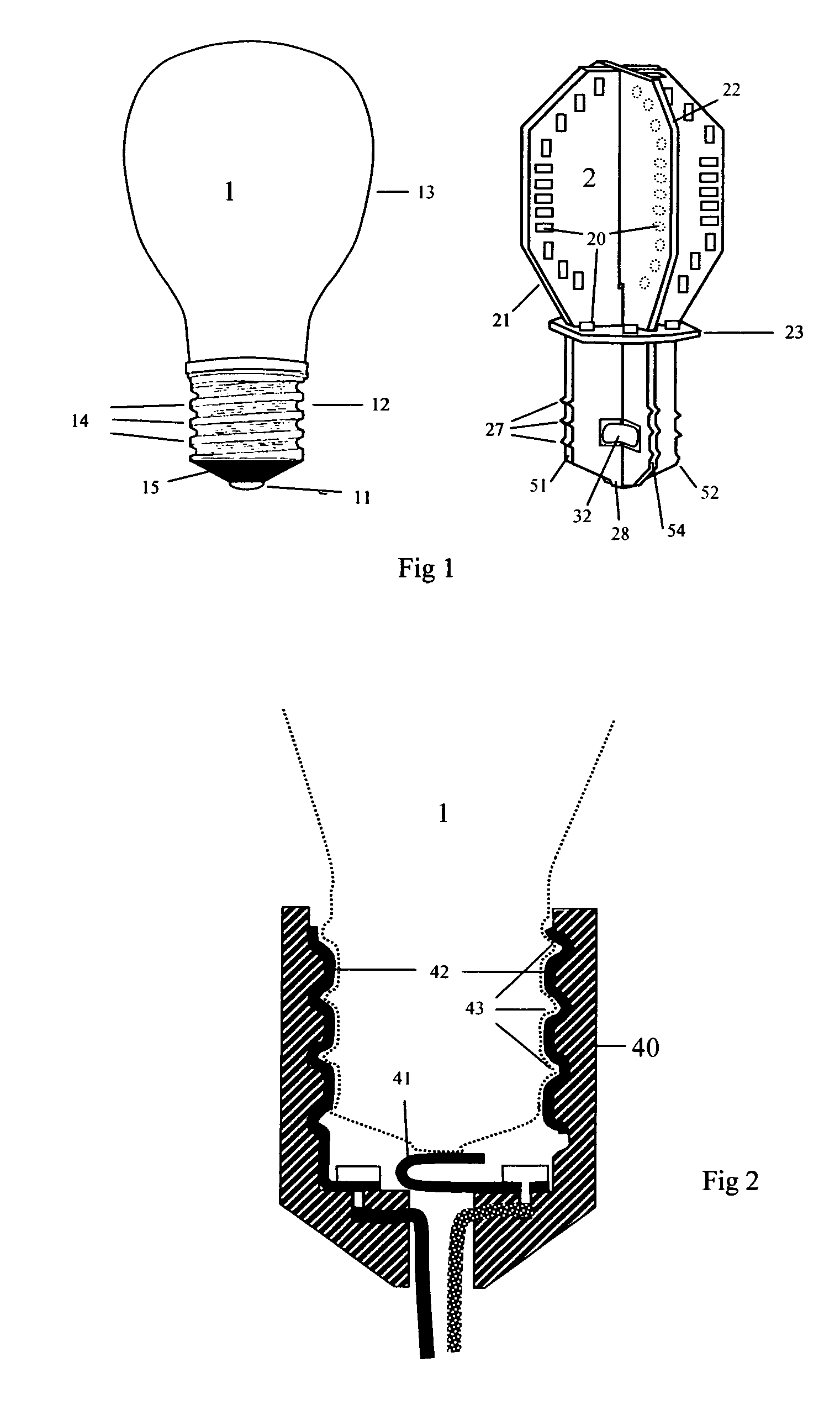
[0029]FIG. 1 shows a side by side comparison between a conventional incandescent light bulb 1 and present invention LED bulb 2. Conventional incandescent light bulb 1 has glass bulb 13 where emits light and screw cap 12 with bight 14 where connects to a bulb socket 40. Bulb cap tip 11 makes contact to contacting foot 41 of said bulb socket.

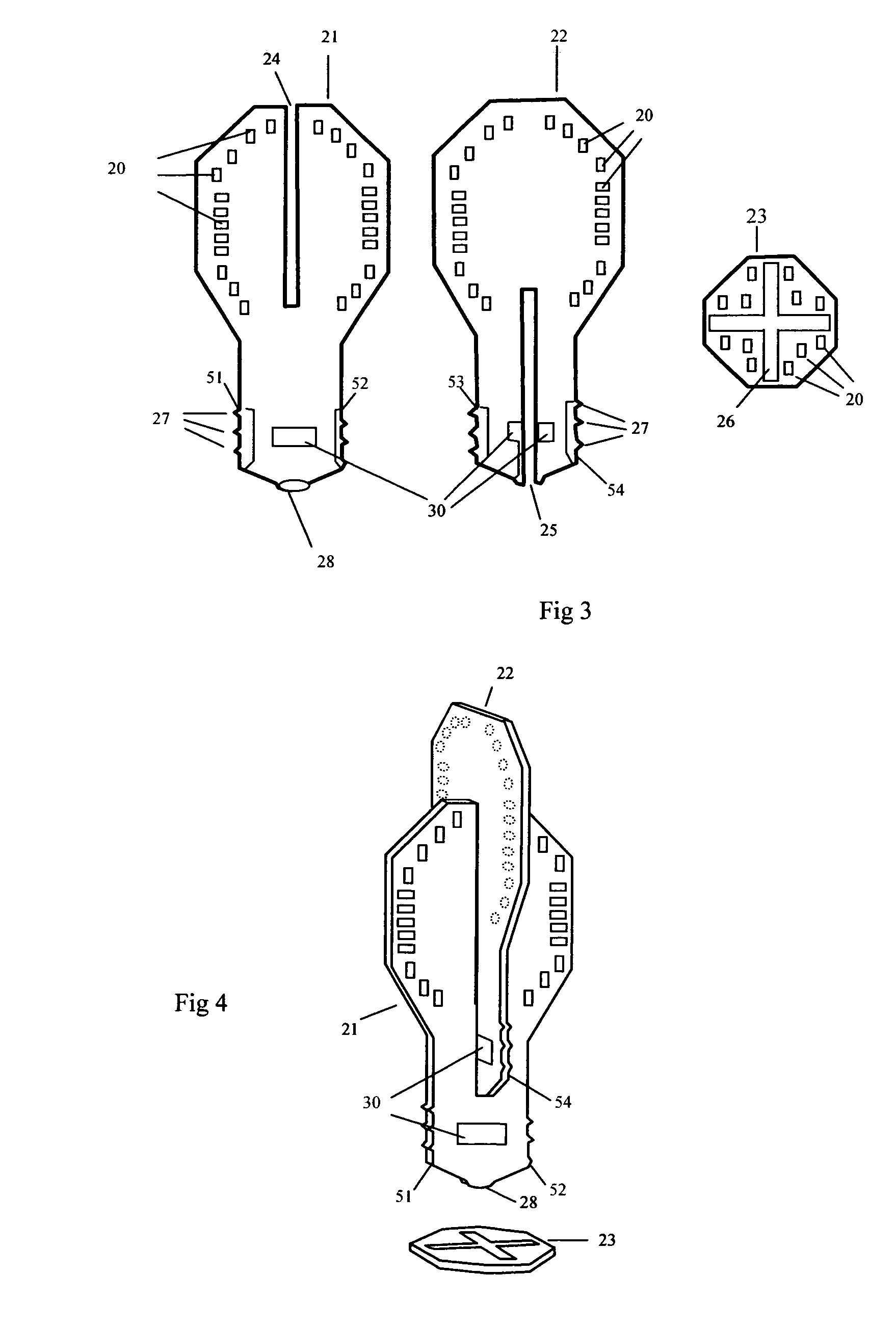
[0030]Showed present invention 2 is comprised of three Printed circuit Boards (PCBs) 21, 22 and 23. This apparatus 2 can be divided into two portions.

[0031]At first portion of this apparatus is equivalent to conventional light bulb cap and is shaped and sized to be fit into a conventional incandescent bulb socket. There are four ...


PUM


Abstract

A light bulb apparatus mounted within existing incandescent bulb sockets is comprised of a plurality of interconnecting printed circuit boards (PCBs). An outline shape of any individual PCB is defined in essentially two dimensions a shape or a size of which may vary from one PCB to another. A first portion of this apparatus is equivalent to light bulb cap and is shaped and sized to be fitted into a conventional incandescent bulb socket. At this portion, at least three PCB side edges are lined up against with an inner side wall of a bulb socket. At least one PCB has a tip edge. A second portion of this apparatus is equivalent to a conventional bulb's glass bulb, and a plurality of light emitting devices are mounted on surfaces of the said PCBs and are connected to the circuit laid on boards.

Description

CROSS-REFERENCE TO RELATED APPLICATIONS[0001]This application is related to and claims priority from U.S. Provisional Patent Application Ser. No. U.S. 61 / 004,066 filed on Nov. 23, 2007.FIELD OF THE INVENTION[0002]The present invention relates, in general, to a light bulb apparatus with utilization of light emitting elements and, more particular, this invention relates to a light bulb with light emitting diodes (LEDs) for use in conventional incandescent light bulb sockets.BACKGROUND OF THE INVENTION[0003]1. Field of the Invention[0004]The present invention relates generally to electrical lighting apparatus, and more particularly to a light bulb apparatus comprising a plurality of light emitting elements, such as light emitting diodes (LEDs), incorporated with printed circuit boards (PCBs) for installation in a conventional incandescent light bulb socket. The present replacement light bulb includes compatible connector and electrical component as required for installation and operati...

Claims


Application Information

Patent Timeline
Patent Type & Authority Patents(United States)
IPC IPC(8): F21S4/00F21K99/00
CPCF21K9/135H05K1/14F21Y2101/02F21Y2111/001F21V19/003H05K3/366H05K2201/048H05K2201/10106F21Y2113/00F21K9/232F21Y2115/10F21Y2107/00
Inventor CHEN, TAIMING
Owner CHEN TAIMING
Why Eureka
Try Eureka