Gas turbine engine having a multi-variable closed loop controller for regulating tip clearance

a closed loop controller and gas turbine engine technology, applied in the direction of machines/engines, leakage prevention, mechanical equipment, etc., can solve the problems of reducing the tip clearance of the rotor blade, not returning a full measure of work to the operation of the turbine, and increasing the associated loss of engine efficiency, so as to increase the efficiency of the engine

Active Publication Date: 2016-02-09
ROLLS ROYCE PLC
View PDF15 Cites 57 Cited by
  • Summary
  • Abstract
  • Description
  • Claims
  • Application Information

AI Technical Summary

Benefits of technology

[0014]It would be desirable to increase the efficiency of engines that have both cooled cooling air systems and tip clearance control systems.
[0020]Advantageously, by determining each of the first and second demand signals on the basis of: (i) a value of the first demand signal at a previous time step, and a measurement or estimate of turbine section component temperature, and (ii) a value of the second demand signal at a previous time step, and a measurement or estimate of tip clearance, inter-relations between the turbine section cooling sub-system and the tip clearance control sub-system can be taken into account, improving the overall efficiency of the engine and / or increasing component life.

Problems solved by technology

However, the cooling air, even if returned into the flow path of the turbine downstream of the combustor, does not return a full measure of work to the operation of the turbine.
Thus, the greater the amount of cooling air that is extracted, the greater the associated loss in engine efficiency.
On exit from the manifold, the air impinges on the outside of the turbine stage casing, causing it to contract and reduce the rotor blade tip clearance.

Method used


Image

  • Gas turbine engine having a multi-variable closed loop controller for regulating tip clearance
  • Gas turbine engine having a multi-variable closed loop controller for regulating tip clearance
  • Gas turbine engine having a multi-variable closed loop controller for regulating tip clearance

Examples


first embodiment

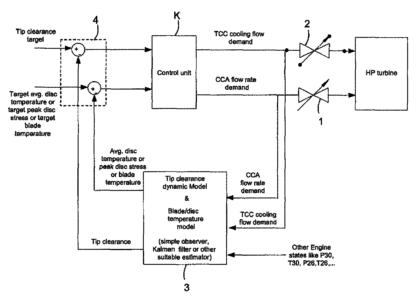
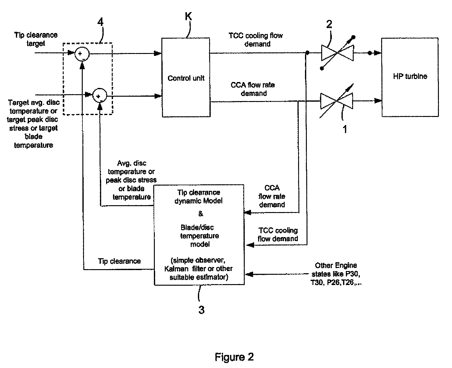
[0053]FIG. 2 shows schematically a system for cooling the high pressure turbine of a gas turbine engine and for providing tip clearance control in the high pressure turbine. The system includes a closed-loop control unit K which is a multivariable controller acting on error variables, s. The control unit embodies a gain matrix, K(s), of the form:

[0054]K⁡(s)=[K11⁡(s)K12⁡(s)K21⁡(s)K22⁡(s)]

to produce a cooled cooling air (CCA) flow rate demand signal and a turbine clearance control (TCC) flow demand signal which are issued to respectively a valve 1 of a turbine section cooling sub-system and a valve 2 of a tip clearance control sub-system. The valves can be, for example, switched vortex valve of the type described in U.S. Pat. No. 3,267,946.

[0055]The gain matrix allows independencies between the CCA and TCC sub-systems to be introduced. The gain matrix can be determined, for example, by a robust control methodology, simple decoupled PI control laws, a linear quadratic regulator contro...

third embodiment

[0064]An alternative to estimating the observer variables is to provide closed-loop control which uses actual variable measurements. FIG. 4 shows schematically a system which implements this approach. A pyrometer and a tip clearance sensor respectively provide measurements of average disc temperature and tip clearance. These measurements are then the observer variables which are sent to the comparator 4 for comparison with respectively a target average disc temperature and a target tip clearance.

[0065]Another option is to adopt the modelling approach for e.g. disc / blade temperature or disc stress and adopt the measurement approach for tip clearance, or vice versa. Indeed, it is possible to improve the accuracy of the observer unit 3 by supplementing the modelling approach of e.g. the first or second embodiment with the direct measurement approach of the third embodiment.


PUM


Abstract

A gas turbine engine has, in flow series, a compressor section, a combustor, and a turbine section. The gas turbine engine further has a system (i) for cooling the turbine section and (ii) for providing tip clearance control between turbine blades of the turbine section and a plurality of circumferentially distributed segments which form an annular shroud surrounding the outer tips of the turbine blades. The system includes a turbine section cooling sub-system which diverts a first cooling air flow received from the compressor section to a heat exchanger and then to the turbine section to cool components thereof. The first cooling air flow by-passes the combustor and is cooled in the heat exchanger. The turbine section cooling subsystem has a first valve arrangement which regulates the first cooling air flow. The system further includes a tip clearance control sub-system which supplies a second cooling air flow to an engine case to which the segments are mounted. The second cooling air flow regulates thermal expansion of the case and thereby controls the clearance between the segments and the outer tips. The tip clearance control sub-system has a second valve arrangement which regulates the second cooling air flow. The system further includes a closed-loop controller which issues first and second demand signals to respectively the first and the second valve arrangements. Each of the first and second demand signals are determined on the basis of: (i) a value of the first demand signal at a previous time step, and a measurement or estimate of turbine section component temperature, and (ii) a value of the second demand signal at a previous time step, and a measurement or estimate of tip clearance.

Description

FIELD OF THE INVENTION[0001]The present invention relates to a closed-loop controller, and, in particular, to a gas turbine engine having a system including such a controller for cooling the turbine section of the gas turbine and for providing tip clearance control.BACKGROUND OF THE INVENTION[0002]With reference to FIG. 1, a ducted fan gas turbine engine generally indicated at 10 has a principal and rotational axis X-X. The engine comprises, in axial flow series, an air intake 11, a propulsive fan 12, an intermediate pressure compressor 13, a high-pressure compressor 14, combustion equipment 15, a high-pressure turbine 16, and intermediate pressure turbine 17, a low-pressure turbine 18 and a core engine exhaust nozzle 19. A nacelle 21 generally surrounds the engine 10 and defines the intake 11, a bypass duct 22 and a bypass exhaust nozzle 23.[0003]The gas turbine engine 10 works in a conventional manner so that air entering the intake 11 is accelerated by the fan 12 to produce two a...

Claims


Application Information

Patent Timeline
Patent Type & Authority Patents(United States)
IPC IPC(8): F01D5/08F01D25/14F02C7/18F01D11/24F01D17/02F01D17/08F02C6/08F02C3/13F02C9/18
CPCF01D11/24F01D5/081F01D17/02F01D17/085F01D25/14F02C3/13F02C6/08F02C7/18F02C7/185F02C9/18F05D2260/205F05D2270/303F05D2270/305F05D2270/44
Inventor BACIC, MARKO
Owner ROLLS ROYCE PLC
Why Eureka
Try Eureka