Multi spool gas turbine system

a gas turbine and multi-spool technology, applied in the direction of machines/engines, clutches, mechanical equipment, etc., can solve the problems of power turbine efficiency decline, power turbine rotor efficiency loss, power turbine efficiency drop, etc., to increase engine efficiency and engine efficiency.

Inactive Publication Date: 2012-07-17
CANDENT TECH
View PDF29 Cites 51 Cited by
  • Summary
  • Abstract
  • Description
  • Claims
  • Application Information

AI Technical Summary

Benefits of technology

[0012]In accordance with another aspect of the invention, the engagement mechanism may be a clutch. In accordance with one embodiment of the invention, the clutch may include a first dog including a first plurality of splines affixed to the first drive shaft, and a second dog having a second plurality of splines affixed to the second drive shaft, wherein the first plurality of splines and second plurality of splines intermesh when the clutch is in an engaged condition. In accordance with another embodiment of the invention, the clutch may include at least one clutch plate adapted and configured to engage at least one pressure plate to couple the first drive shaft to the second drive shaft. The clutch may also be a hydraulic clutch. If desired, the engagement mechanism may allow a controlled amount of slippage between the first drive shaft and the second drive shaft.
[0016]In accordance with yet another aspect of the invention, the gas turbine engine disclosed herein may further include a heat exchanger disposed between and in fluid communication with the low pressure compressor and the high pressure compressor. The heat exchanger is preferably adapted to remove heat from fluid passing from the low pressure compressor to the high pressure compressor to increase the efficiency of the engine. If desired, the engine may additionally or alternatively include a heat exchanger adapted to direct heat from the exhaust of the engine to fluid leaving the high pressure compressor, thereby increasing engine efficiency.

Problems solved by technology

However, for applications such as the next generation of advanced helicopters and ground vehicles, the ability to efficiently deliver power at lower output shaft speeds remains a challenge.
This approach is satisfactory when the output speed of the system is within a narrow speed range, but as the output speed of the engine drops, the power turbine efficiency falls off.
Attempting to operate a conventional free turbine engine at output shaft speeds lower than 75% typically results in a loss of power turbine rotor efficiency.
What physically occurs is that the turbine loading, in terms of work per unit airflow remains constant, while the speed decreases, robbing the turbine of work capability.
This results in overloading of the turbine and reduced turbine efficiency.
However, these prior art systems are all based on concepts in which there was a fundamental speed difference between the shafting systems being coupled, and therefore these systems required the addition of gear trains to accommodate these speed differences.
However, such systems, in employing intermediate gearing, add significant expense complexity and weight to the system.

Method used


Image

  • Multi spool gas turbine system
  • Multi spool gas turbine system
  • Multi spool gas turbine system

Examples


Embodiment Construction

[0025]Reference will now be made in detail to the present preferred embodiments of the invention, an example of which is illustrated in the accompanying drawings. The method and corresponding steps of the invention will be described in conjunction with the detailed description of the system.

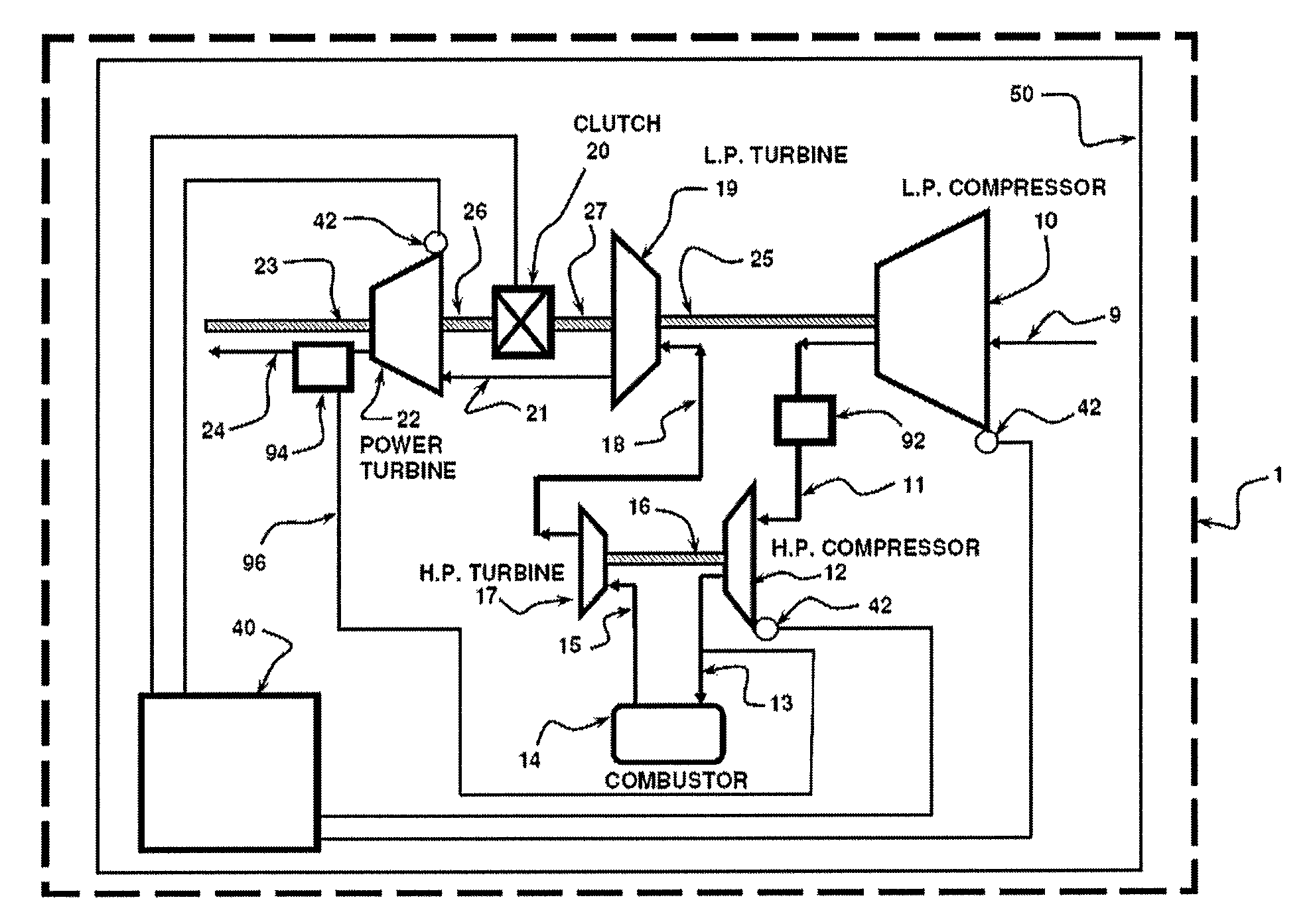
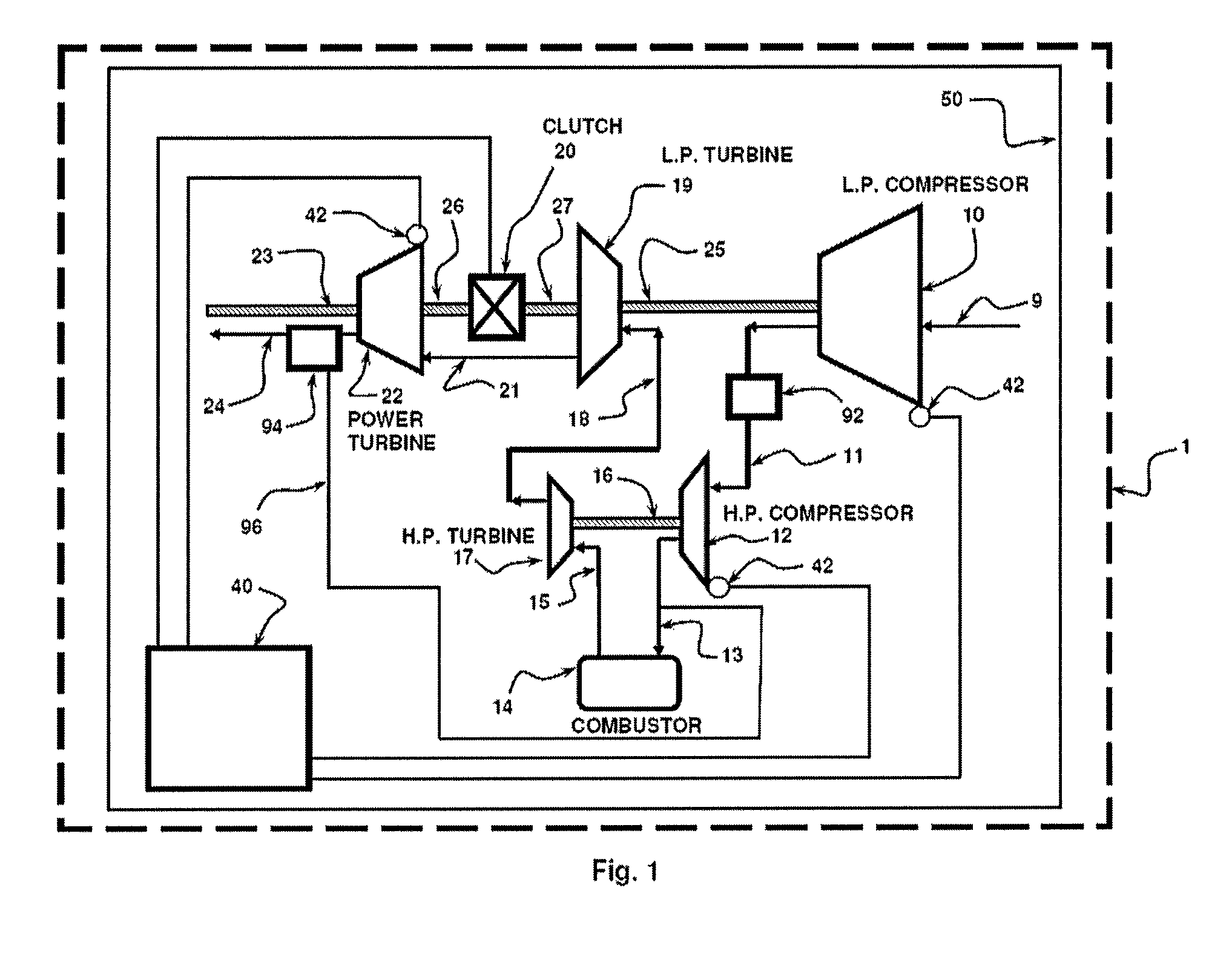
[0026]The devices and methods presented herein may be used in a variety of contexts, including vehicle propulsion and / or power generation. The present invention is particularly suited for use in helicopters that operate with relatively low and / or variable rotor speeds. The present invention provides advantages in cost and simplicity relative to prior art by designing a gas turbine in which the low pressure spool and the output shafting may be directly selectively coupled to improve the part power efficiency of the engine.

[0027]In accordance with the invention, a gas turbine engine is provided, including an air inlet in fluid communication with a compressor, a combustor, a compressor turbine, and ...


PUM


Abstract

A gas turbine engine is provided, including an air inlet in fluid communication with a compressor, a combustor, a compressor turbine, and a power turbine. The compressor and compressor turbine may be mounted on a first drive shaft, and the power turbine may be mounted on a second shaft. The engine further includes an engagement mechanism adapted to selectively engage the first drive shaft to the second drive shaft, wherein the first drive shaft and second drive shaft rotate at substantially the same speed when the engagement mechanism is engaged. The disclosed multi-spool gas turbine engine provides improved part power fuel consumption at reduced output shaft speeds. The proposed invention can relate to turbines with two or more gas generator spools.

Description

CROSS-REFERENCE TO RELATED APPLICATION[0001]This application claims the benefit of priority from U.S. Provisional Patent Application Ser. No. 60 / 705,028 filed Aug. 3, 2005, the disclosure of which is incorporated by reference herein in its entirety.BACKGROUND OF THE INVENTION[0002]1. Field of the Invention[0003]The present invention relates to gas turbine engines, and relates more particularly to an improved gas turbine engine and method and control system therefore particularly useful as the power plant for a ground vehicle or advanced rotorcraft.[0004]2. Description of Related Art[0005]A variety of gas turbine devices are known in the art for generating useful work by combusting fuel mixtures. Of such devices, many gas turbine are directed to powering vehicles, such as ground, water and air vehicles.[0006]Gas turbine engine fuel efficiency has improved in recent years to levels typically associated with reciprocating engines. In most cases, gas turbine engines have displaced recip...

Claims


Application Information

Patent Timeline
Patent Type & Authority Patents(United States)
IPC IPC(8): F02C1/06
CPCF02C3/10F02C7/08F02C7/36F16D25/061F16D25/0638Y02T50/671F05D2220/329F05D2260/403F05D2270/708F05D2270/304F05D2270/303Y02T50/60
Inventor PAPANDREAS, EMANUEL
Owner CANDENT TECH
Why Eureka
Try Eureka