Convergent/divergent nozzle with modulated cooling

a technology of modulated cooling and divergent nozzles, which is applied in the direction of marine propulsion, combustion types, vessel construction, etc., can solve the problems of reducing engine efficiency, and achieve the effects of increasing non-afterburning engine efficiency, reducing pressure and momentum loss, and increasing engine efficiency

Active Publication Date: 2006-04-25
RTX CORP
View PDF19 Cites 53 Cited by
  • Summary
  • Abstract
  • Description
  • Claims
  • Application Information

AI Technical Summary

Benefits of technology

[0007]Each divergent flap includes a multiple of cooling channels. Cooling airflow enters each channel through a corresponding intake and exits each channel through a set of discharge ports. The divergent flap intakes are arranged downstream of the hinge axis such that the intakes are selectively covered by the adjacent divergent flap seals. As the nozzle transitions between the open position and the closed position, the divergent flap seals move relative to the divergent flap longitudinal axis to modulate the cooling airflow that enters the separate intakes. A relatively large quantity of cooling airflow is directed through all the intakes to provide significant convective cooling of the divergent section during afterburner operations. In a relatively closed or non-afterburning position, the divergent flap seals are constricted toward the divergent flap longitudinal axis such that a lesser number of intakes are exposed to the cooling airflow. The cooling airflow which does not pass through the divergent flaps due to the blocked intakes combines with the core airflow and increases non-afterburning engine efficiency due in part to the associated decrease in pressure and momentum loss and increases efficiency of the engine.
[0008]The present invention therefore provides adequate cooling for the convergent and divergent sections while efficiently utilizing the cooling air

Problems solved by technology

The diversion of excess cooling air from the core airflow decreases the efficiency of the engine.

Method used


Image

  • Convergent/divergent nozzle with modulated cooling
  • Convergent/divergent nozzle with modulated cooling
  • Convergent/divergent nozzle with modulated cooling

Examples


Embodiment Construction

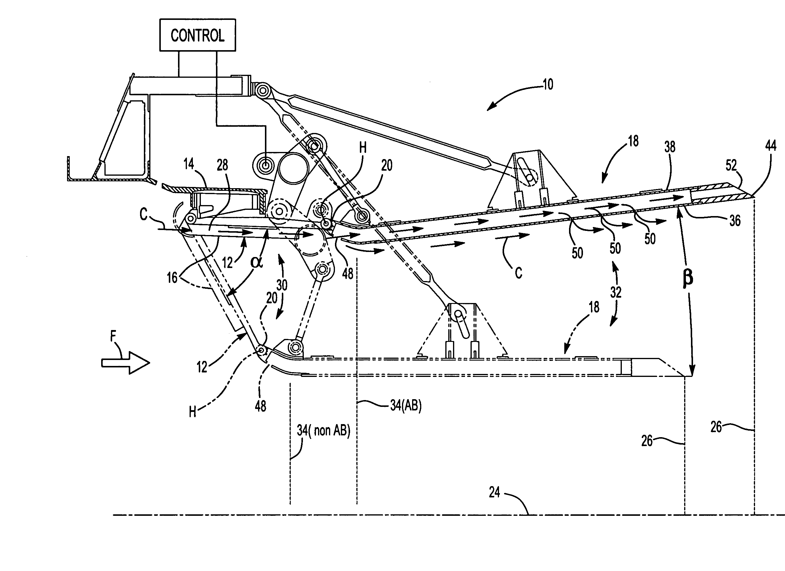
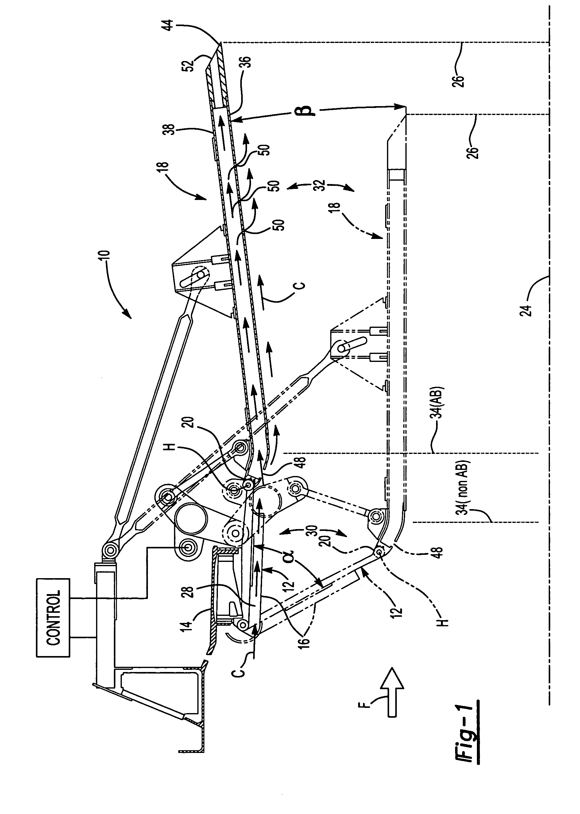
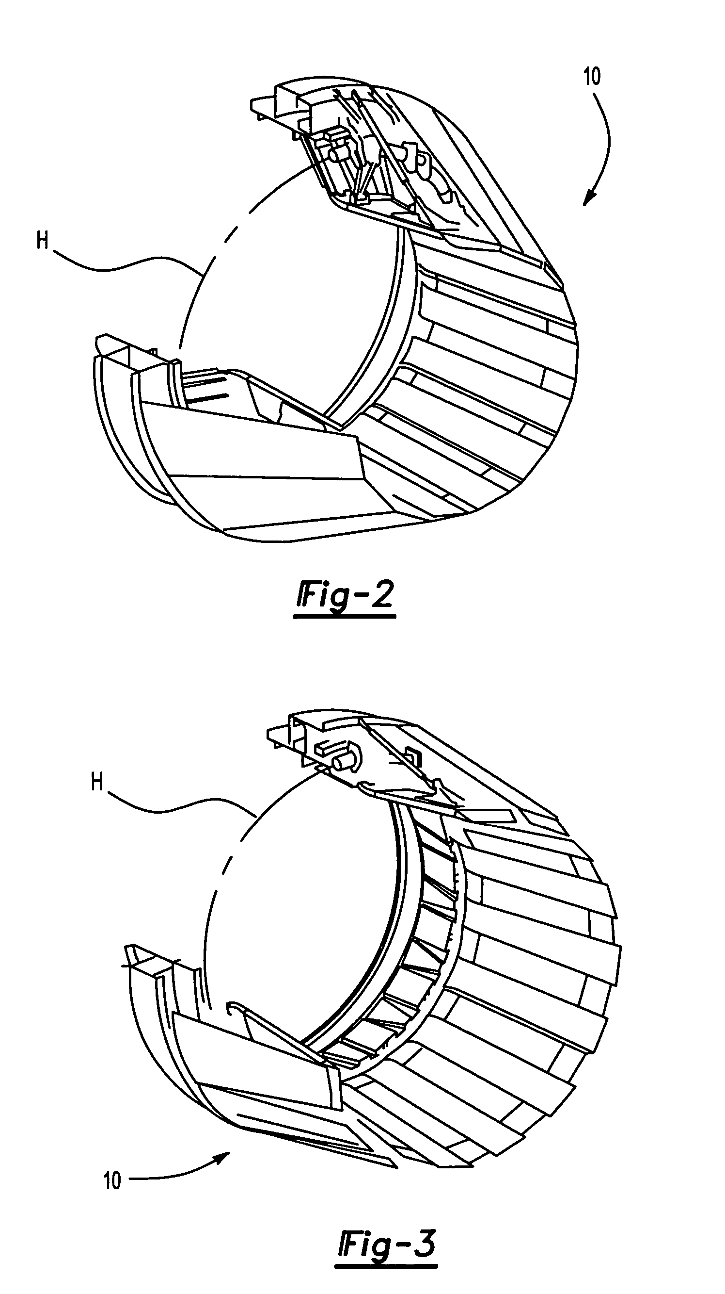
[0019]FIG. 1 illustrates a sectional view of a nozzle system 10 for a gas turbine engine. FIG. 1 depicts the nozzle 10 in both an open position (solid lines and FIG. 2), which is used during afterburning operation, and in a closed position (phantom lines and FIG. 3), which is used during non-afterburning operation.

[0020]During operation, a control system governs the angular orientations of the convergent and divergent flaps to adjust the nozzle throat area and discharge area. The convergent flaps are positionable over a range of angular orientations α, and the divergent flaps are similarly positionable over a corresponding spectrum of angular orientations β.

[0021]The nozzle includes a plurality of circumferentially distributed convergent flaps 12, each pivotably connected to a stationary frame 14 and each having a liner panel 16 secured thereto. A plurality of circumferentially distributed divergent flaps 18 are pivotably connected at a joint 20 to the aft ends of the convergent fla...


PUM


Abstract

A nozzle system includes a multiple of circumferentially distributed convergent flaps, divergent flaps and inter-flap seals which circumscribe an engine centerline and define the radial outer boundary of a gas path. Each divergent flap includes a multiple of cooling channels with respective intakes and outlets. As the nozzle transitions between positions, the divergent flap seals move relative a divergent flap longitudinal axis to modulate the cooling airflow which enters the separate intakes.

Description

BACKGROUND OF THE INVENTION[0001]The present invention relates to gas turbine engines having convergent / divergent nozzles, and more particularly to a nozzle divergent section cooling arrangement.[0002]An exhaust nozzle optimizes the thrust produced within a gas turbine engine. In augmented gas turbine engines, convergent / divergent (CID) nozzles provide a multitude of nozzle positions. Flaps circumferentially distributed aft of the augmentor or exhaust duct form the convergent and divergent sections for which the nozzle is named. Flap seals disposed between adjacent flaps minimize gas leakage between flaps in both sections. The convergent section is pivotally connected to the augmentor or exhaust duct and to the divergent section. The divergent section is pivotally connected to the convergent section and to an external fairing positioned radially outboard of the divergent section. The opposite end of the external fairing is pivotally attached to a static outer casing which surrounds ...

Claims


Application Information

Patent Timeline
Patent Type & Authority Patents(United States)
IPC IPC(8): B05B7/16B05B1/24B05B12/00B63H11/10B05C1/00F02K1/12F02K1/82
CPCF02K1/1223F02K1/822Y02T50/675Y02T50/60
Inventor MURPHY, MICHAEL J.COWAN, CURTIS C.PAUL, STEPHEN A.ALLORE, JAMES P.HARRIS, MEGGAN
Owner RTX CORP
Why Eureka
Try Eureka