Switchable directional coupler for use with RF devices

a directional coupler and switchable technology, applied in the field of wireless communication, can solve the problems of increasing the physical size and weight of the reader, being unsuitable, and being a complex and expensive device, and achieve the effect of effectively removing the directional coupler and its associated losses and imposing minimal additional losses

Inactive Publication Date: 2007-01-11
TRIQUINT SEMICONDUCTOR
View PDF99 Cites 52 Cited by
  • Summary
  • Abstract
  • Description
  • Claims
  • Application Information

AI Technical Summary

Benefits of technology

[0014] Therefore, there is a need for a mechanism to effectively remove the directional coupler and its associated losses from the receive chain of a

Problems solved by technology

In a conventional homodyne reader, such as the one described in U.S. Pat. No. 2,114,971, two separate decoupled antennas for transmission (TX) and reception (RX) are used, resulting in increased physical size and weight of the reader, and are thus not desirable.
Because circulators are usually complex and expensive devices employing non-reciprocal magnetic materials, the use of a directional coupler is often preferred for low-cost radios.
C

Method used


Image

  • Switchable directional coupler for use with RF devices
  • Switchable directional coupler for use with RF devices
  • Switchable directional coupler for use with RF devices

Examples


Embodiment Construction

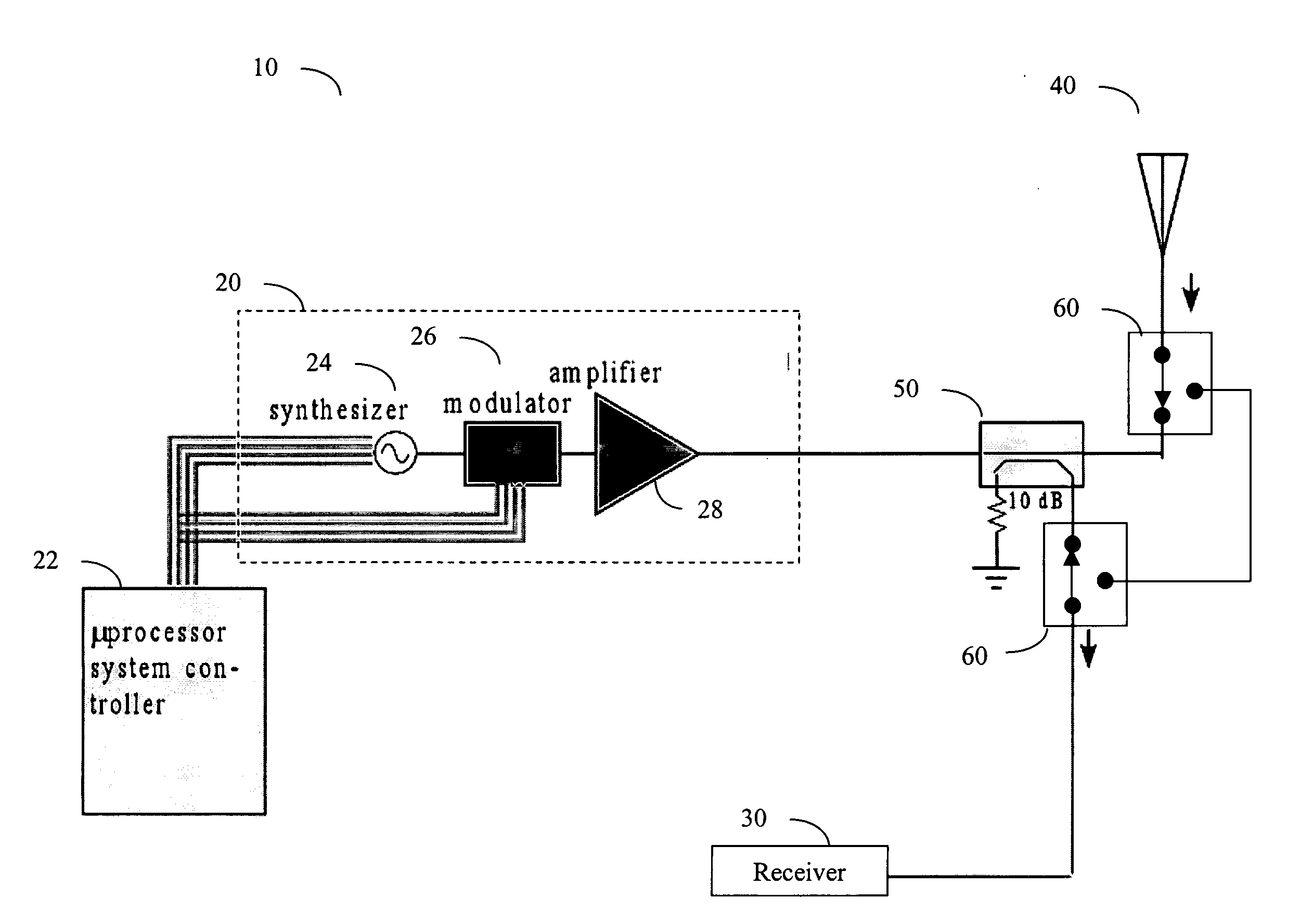
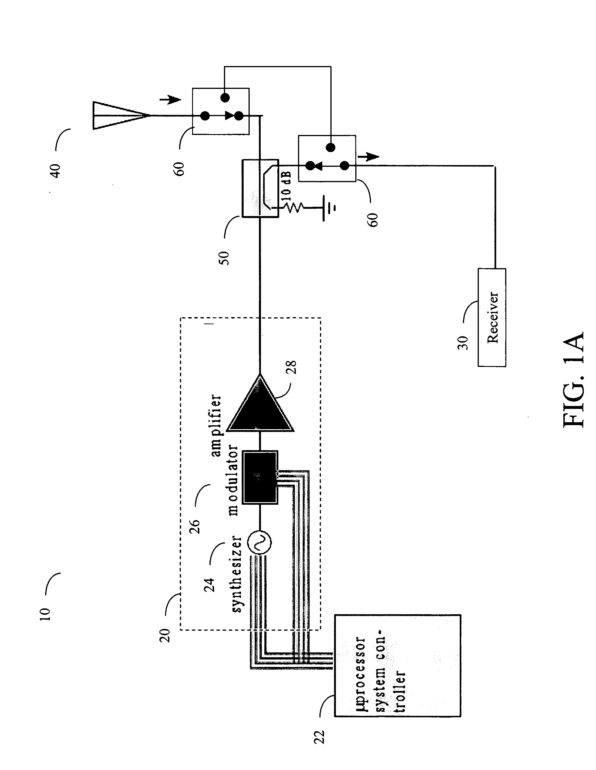
[0023]FIG. 1A shows an RF radio 10 having an RF transmitter 20 and an RF receiver 30 connected to an antenna 40 via a directional coupler 50. The transmitter 20 is shown to comprise a microprocessor system controller 22, a frequency synthesizer 24, an optional modulator 26, and an amplifier 28. A pair of RF switches 60 may be used to direct a received signal around the directional coupler when the radio 10 is used as a receiver. The switches 60 are usually relatively complex double-throw switches, such as conventional Single Pole and Double Throw (SPDT) switches. An SPDT switch can be on in both positions, and is sometimes called a changeover switch. In the example shown in FIG. 1A, the switches 60 are used to couple the receiver 30 to the antenna 40 via the directional coupler 50 in one position and to allow a received signal to bypass the directional coupler 50 in the other position. By bypassing the directional coupler 50, the received signal does not suffer an exemplary 10 dB lo...


PUM


Abstract

The embodiments of the present invention provide a directional coupler switchable between a normal state and a bypass state. In one embodiment, the directional coupler comprises shunt switches for switching between the normal state and the bypass state, and first and second transmission lines each extending between first and second ends, wherein the shunt switches comprises a first switch coupled to the first end of the first transmission line, a second switch coupled to the first end of the first transmission line, and a third switch coupled between the second end of the first transmission line and the second end of the second transmission line.

Description

CROSS REFERENCE TO RELATED APPLICATIONS [0001] The present application claims the benefit of and priority under 35 U.S.C. 120 to U.S. patent application Ser. No. 11 / 021,302 entitled “Multiprotocol RFID Reader,” U.S. patent application Ser. No. 11 / 021,946 entitled “Linearized Power Amplifier Modulator in an RFID Reader,” U.S. patent application Ser. No. 11 / 021,539 entitled “Integrated Switching Device for Routing Radio Frequency Signals,” all of which were filed on Dec. 23, 2004.FIELD OF THE INVENTION [0002] The present invention relates in general to wireless communications using radio-frequency signals, and particularly to directional couplers in radio-frequency devices. BACKGROUND OF THE INVENTION [0003] A wireless device that is able to communicate with others using radio frequency (RF) signals is usually equipped with an RF transmitter and receiver. An RF receiver employing a so-called superheterodyne architecture typically includes an antenna that transforms electromagnetic wav...

Claims


Application Information

Patent Timeline
IPC IPC(8): G08B13/14
CPCH01P5/04
Inventor BELLANTONI, JOHN VINCENT
Owner TRIQUINT SEMICONDUCTOR
Why Eureka
Try Eureka