
System and method to eliminate transition losses in DC/DC converters

a technology of dc/dc converter and transition loss, applied in the direction of electric variable regulation, process and machine control, instruments, etc., can solve the problems of capacitance loss, transition loss, power dissipation loss in switching regulator, etc., to reduce transition loss, eliminate loss, and remove current loss factor

Active Publication Date: 2017-03-28
MAXIM INTEGRATED PROD INC
View PDF8 Cites 0 Cited by
  • Summary
  • Abstract
  • Description
  • Claims
  • Application Information

AI Technical Summary

Benefits of technology

The invention introduces a method for eliminating losses in power MOSFETs by using continuous current converter switching. The method includes a novel ZVS method, a novel type of ZCS switching, and a novel type of switching called NCS. The invention also eliminates losses associated with body diode reverse recovery currents. The technical effect of the invention is reduced transition losses and zero loss of voltage during switching. This results in more efficient power conversion and reduced circuit complexity.

Problems solved by technology

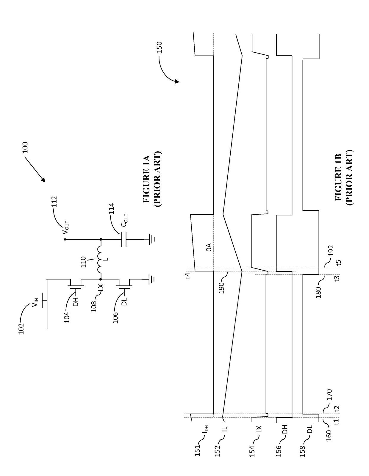
Aside from conduction losses in the turned on active devices, which are typically transistor power switches, one major source of power dissipation in switching regulators are transition losses.
There are two types of transition losses that occur during the switching process, the first type is capacitive loss resulting from charging and discharging a parasitic capacitance at the switching node of the converter.
However, existing ZVS or ZCS topologies have major drawbacks.
However, these approaches create more problems than they solve and do not result in higher system efficiency at higher ripple currents due to increased conduction losses associated with resonant or critical conduction topologies.

Method used


Image

  • System and method to eliminate transition losses in DC/DC converters
  • System and method to eliminate transition losses in DC/DC converters
  • System and method to eliminate transition losses in DC/DC converters

Examples


Embodiment Construction

[0024]In the following description, for the purpose of explanation, specific details are set forth in order to provide an understanding of the invention. It will be apparent, however, to one skilled in the art that the invention may be practiced without these details. One skilled in the art will recognize that embodiments of the present invention, described below, may be performed in a variety of ways and using a variety of means. Those skilled in the art will also recognize that additional modifications, applications, and embodiments are within the scope thereof, as are additional fields in which the invention may provide utility. Accordingly, the embodiments described below are illustrative of specific embodiments of the invention and are meant to avoid obscuring the invention.

[0025]Reference in the specification to “one embodiment” or “an embodiment” means that a particular feature, structure, characteristic, or function described in connection with the embodiment is included in ...


PUM


Abstract

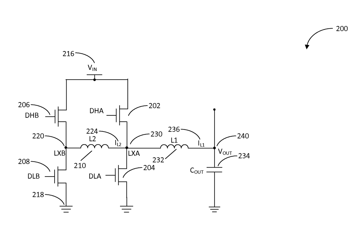
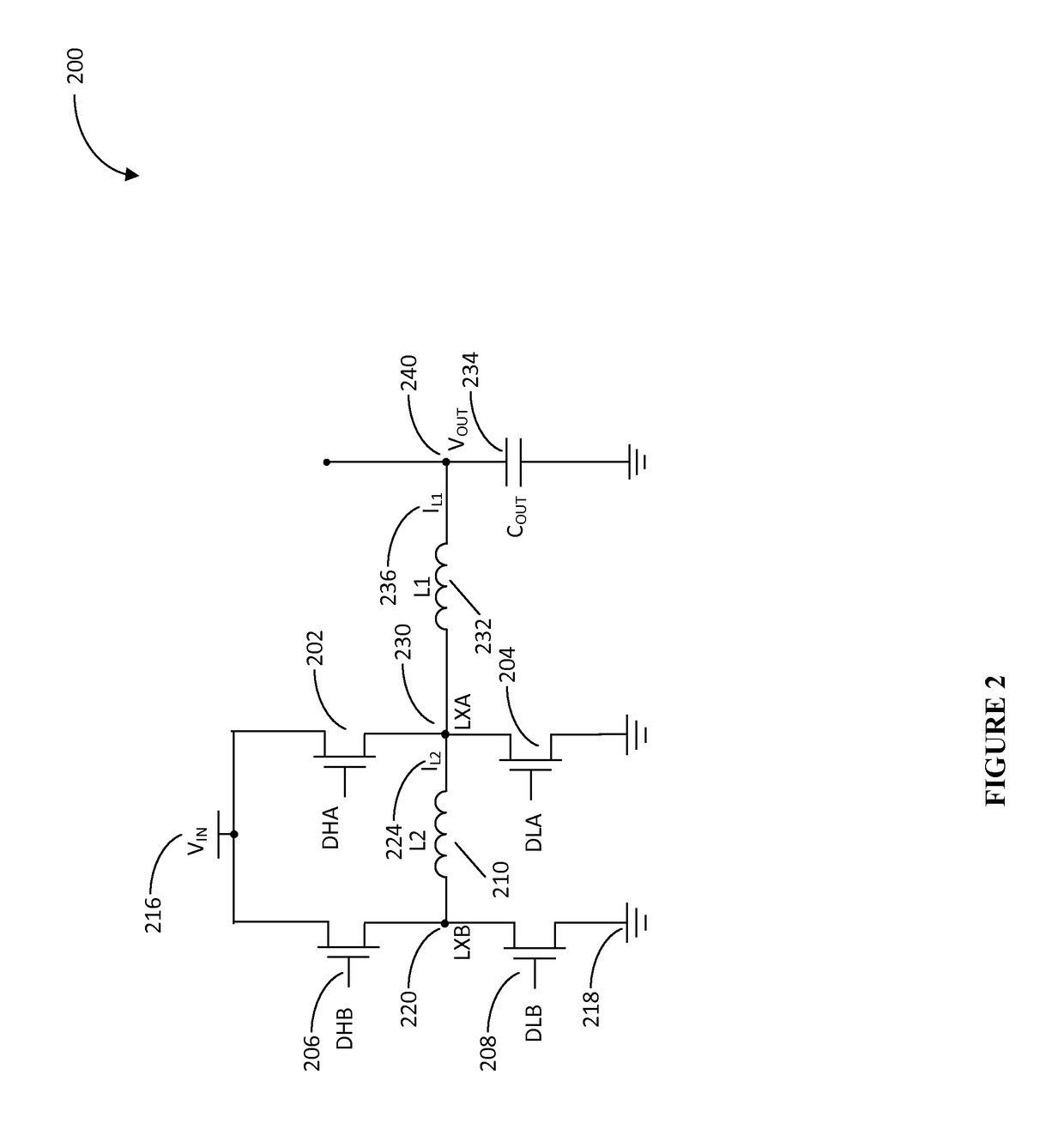
Various embodiments of the invention reduce switching losses associated with existing non-zero volt switching and non-zero current switching in DC / DC converters without the need for a resonant design. Certain embodiments of the invention provide for improved efficiency by reducing switching losses related to the simultaneous presence of current and voltage across high power switching devices. In certain embodiments, this is accomplished by adding a relatively small inductor and two switching elements to various switching regulator topologies. Energy stored in the inductor is used to transition the output of the switching converter to achieve zero volt switching and zero current switching.

Description

BACKGROUND[0001]A. Technical Field[0002]The present invention relates to inductive switching converters and, more particularly, to systems, devices, and methods of utilizing zero-current and zero-voltage switching to reduce transition losses in DC / DC converters.[0003]B. Background of the Invention[0004]The electronics industry has continually demanded higher switching regulator efficiencies. Switching regulators transfer energy from a given input voltage level to a higher or lower output voltage level for delivery to a load. Inductive switching converters take advantage of in important physical property of inductors, the resistance to any changes to the current the inductor carries, in order to transform an input voltage to a desired output voltage. The level of the output voltage is adjusted by controlling the operation of active switching elements within the switching regulator.[0005]Typical efficiencies of DC / DC converters have reached about 96%, such that a reduction of power lo...

Claims


Application Information

Patent Timeline
Patent Type & Authority Patents(United States)
IPC IPC(8): G05F1/00H02M3/155H02M3/158H02M1/00
CPCH02M3/155H02M3/158Y02B70/1425Y02B70/1491H02M2001/0054Y02B70/10H02M1/0054H02M1/0058
Inventor LOCASCIO, JAMES JASON
Owner MAXIM INTEGRATED PROD INC
Learn More