Power steering system

a technology of power steering and steering shaft, which is applied in the direction of couplings, rotary clutches, fluid couplings, etc., can solve the problems of increasing fuel consumption, increasing fuel consumption, and significant fuel consumption, so as to improve vehicle fuel efficiency, reduce cost, and eliminate losses

Inactive Publication Date: 2007-07-10
GM GLOBAL TECH OPERATIONS LLC
View PDF17 Cites 26 Cited by
  • Summary
  • Abstract
  • Description
  • Claims
  • Application Information

AI Technical Summary

Benefits of technology

[0009]One advantage of the present invention is that a power steering system is provided for a vehicle. Another advantage of the present invention is that the power steering system adopts direct control of the speed of the hydraulic pump by using a fluid coupling integrated between the accessory drive shaft and the hydraulic power steering pump. Yet another advantage of the present invention is that the power steering system provides continually adjustable speed by controlling the torque transmitted from the drive shaft to that of the power steering pump. Still another advantage of the present invention is that the hydraulic power steering system improves vehicle fuel efficiency due to elimination of losses resulting from double energy conversion in a conventional electro-hydraulic power steering system.
[0010]A further advantage of the present invention is that, in one embodiment, the power steering system reduces cost due to a relatively simple low current controller replacing the costly high-current power-electronics of a conventional electro-hydraulic power steering system. Yet a further advantage of the present invention is that the power steering system provides variable power steering assist by controlling the pump speed of the hydraulic pump. Still a further advantage of the present invention is that the magneto-rheological hydraulic power steering system may have reduced mass due to the elimination of an electric motor and high current power electronics as in electro-hydraulic power systems.
[0011]Another advantage of the present invention is that the power steering system improves reliability due to reduced number of components and less stress on the mechanical parts of the hydraulic pump. Yet another advantage of the present invention is that the power steering system may have less packaging issues by having, in one embodiment, a stationary coil magneto-rheological fluid-based coupling integrated into the power steering pump pulley, thereby reducing cost. Still another advantage of the present invention is that the power steering system may have a symmetric rotor double bearing arrangement that balances the side loads on the pulley from the belt. A further advantage of the present invention is that the magneto-rheological hydraulic power steering system enables fuel economy enhancement by reducing the power steering pump torque to a minimum when steering assist is not required and offers speed variable effort at no additional cost. Still a further advantage of the present invention is that the power steering system also enhances the life of the pump as it is working with less torque for more than 90% of the time when power assist is not needed.

Problems solved by technology

Since the power steering pump is driven directly by the engine using a belt, its speed is determined by that of the engine and it operates continuously as long as the engine is running, resulting in continuous losses due to constant circulation of the hydraulic fluid through the steering gear.
This results in increased fuel consumption due to continuous operation of the power steering pump at speeds dictated by the engine speed, even when no steering assist is required.
In addition, the power steering pump has to provide the required flow and pressure for the worst case engine speed, which could be near idle, under static steering conditions, contributing to significant fuel consumption.
This results in much higher pump flow at higher engine speeds further increasing the losses in the hydraulic power steering system, which results ultimately in increased fuel consumption.
However, the electrohydraulic power steering system needs a costly high power electric motor, power electronics for controlling speed of the electric motor, and a reliable electrical power supply (including an engine driven alternator and battery).
The overall losses of the conventional electrohydraulic power steering system include losses through the engine alternator, power electronics, electric motor, and power steering pump.

Method used


Image

  • Power steering system
  • Power steering system
  • Power steering system

Examples


Embodiment Construction

)

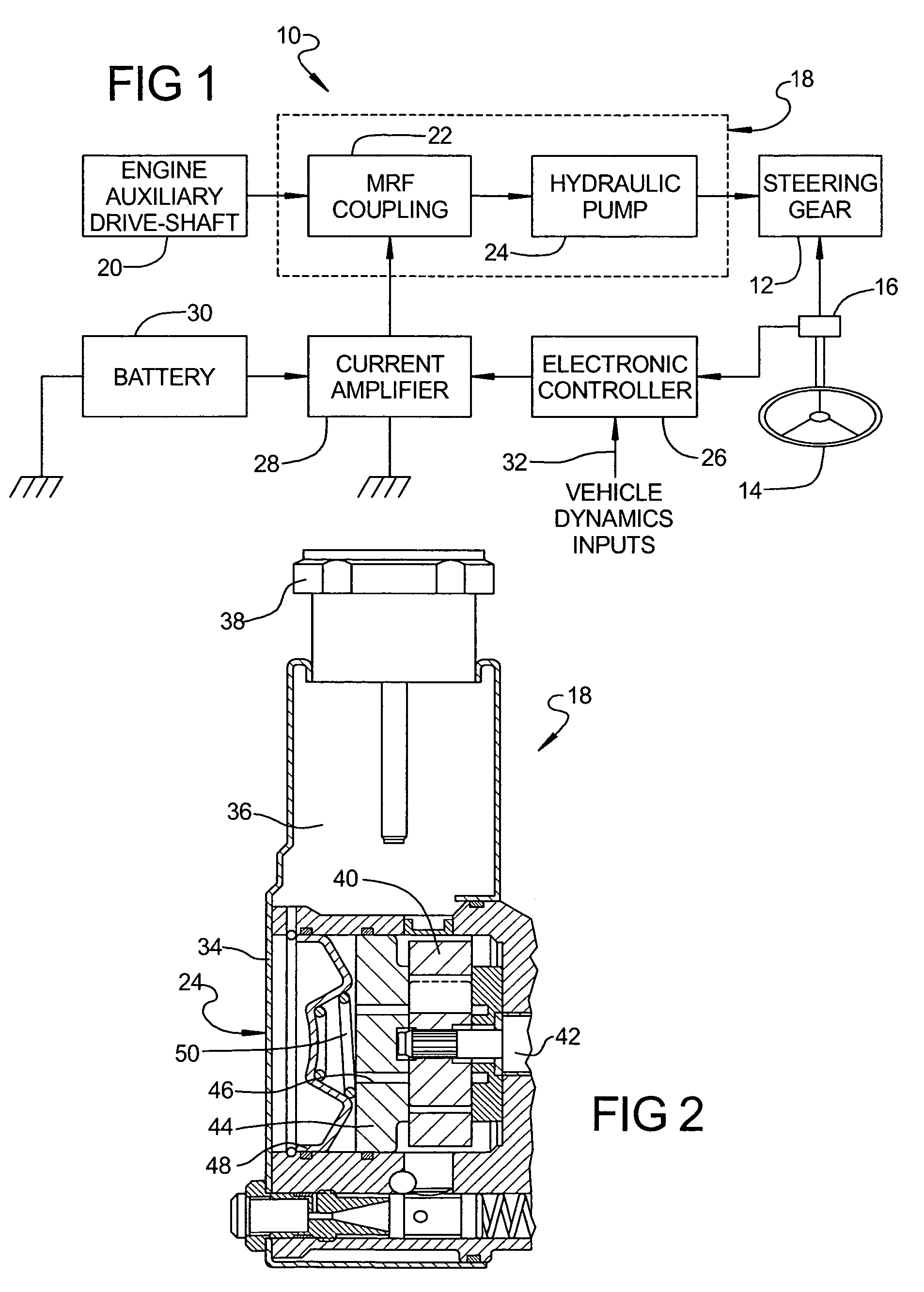
[0019]Referring to the drawings and in particular FIG. 1, one embodiment of a magneto-rheological hydraulic power steering system 10, according to the present invention, is shown for a vehicle (not shown) such as a motor vehicle or automotive vehicle. The magneto-rheological hydraulic power steering system 10 includes a steering gear 12 and a steering wheel 14 operatively connected to the steering gear 12. The magneto-rheological hydraulic power steering system 10 also includes at least one steering wheel sensor 16 operatively connected to the steering wheel 14 to sense angle and / or torque of the steering wheel 14. It should be appreciated that the steering gear 12, steering wheel 14, and steering wheel sensor 16 are conventional and known in the art.

[0020]The magneto-rheological hydraulic power steering system 10 includes a magneto-electrohydraulic power steering pump, generally indicated at 18, operatively connected to the power steering gear 12 and a drive-shaft such as an auxil...


PUM


Abstract

A power steering system for a vehicle includes a hydraulic pump connected to a power steering gear of the vehicle and a fluid coupling interconnecting a drive shaft of an engine of the vehicle with the hydraulic pump. The power steering system also includes an electronic controller operable to provide a variable control signal based on received input and an amplifier to receive the variable control signal and energize the fluid coupling in response thereto to vary torque transmitted via the fluid coupling.

Description

CROSS-REFERENCE TO RELATED APPLICATION(S)[0001]The present application claims the benefit of copending U.S. Provisional Patent Application Ser. No. 60 / 607,639, filed Sep. 7, 2004 and is a continuation-in-part of U.S. patent application Ser. No. 10 / 408,752, filed Apr. 7, 2003, now U.S. Pat. No. 6,920,753.TECHNICAL FIELD[0002]The present invention relates generally to power steering systems for vehicles and, more particularly, to a magneto-rheological hydraulic power steering system for a vehicle.BACKGROUND OF THE INVENTION[0003]It is known to provide a power steering system for a vehicle such as a motor vehicle to assist a driver in steering the motor vehicle. Typically, the power steering system is of a hydraulic type. The hydraulic power steering system employs an engine driven hydraulic power steering pump for generating pressurized fluid that is coupled to a hydraulic steering gear of the motor vehicle. Since the power steering pump is driven directly by the engine using a belt, ...

Claims


Application Information

Patent Timeline
Patent Type & Authority Patents(United States)
IPC IPC(8): F16D37/02B62D5/06B62D5/065
CPCB62D5/0478B62D5/063B62D5/065F16D37/008F16D37/02F16D2037/004F16D2500/10418
Inventor NAMUDURI, CHANDRA S.MURTY, BALARAMA V.TONG, JIE
Owner GM GLOBAL TECH OPERATIONS LLC
Why Eureka
Try Eureka