Solid state electrochemical devices

a solid-state electrochemical and cell technology, applied in the field of electrochemical cell stacks, can solve the problems of increasing size, increasing the size, and the inability of cells to generate voltages greater than about 1 volt, so as to increase the fuel utilization rate, increase the power packing density, and consume rapid

Inactive Publication Date: 2004-12-23
CONNECTICUT UNIV OF THE
View PDF9 Cites 69 Cited by
  • Summary
  • Abstract
  • Description
  • Claims
  • Application Information

AI Technical Summary

Benefits of technology

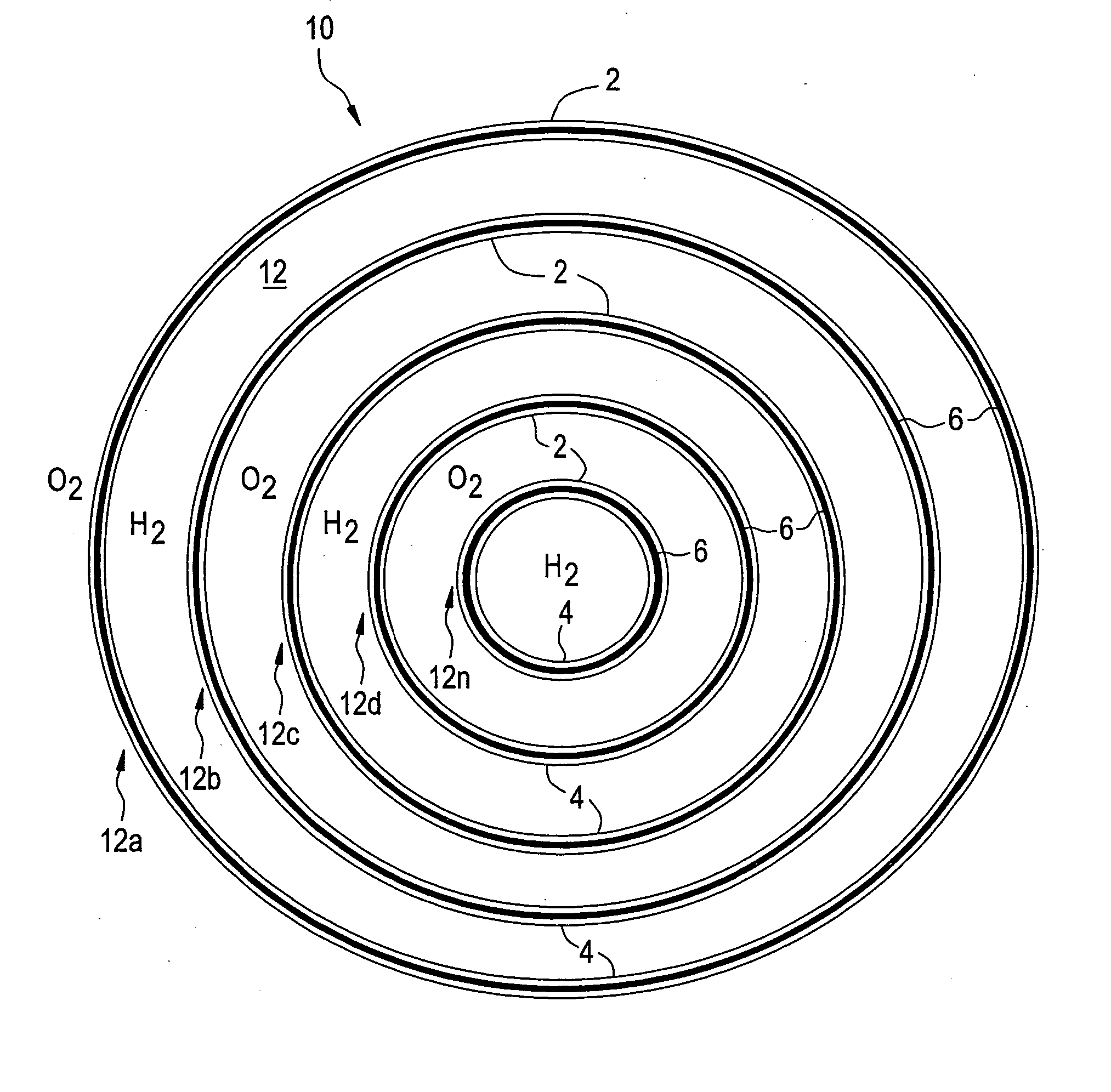
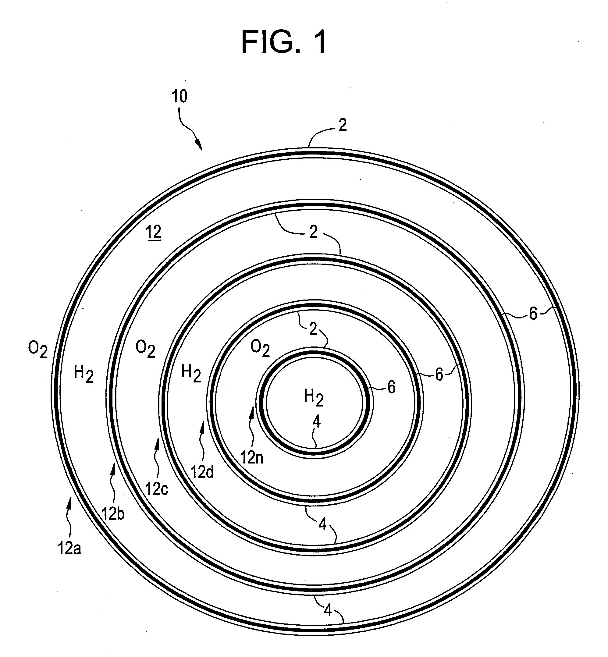
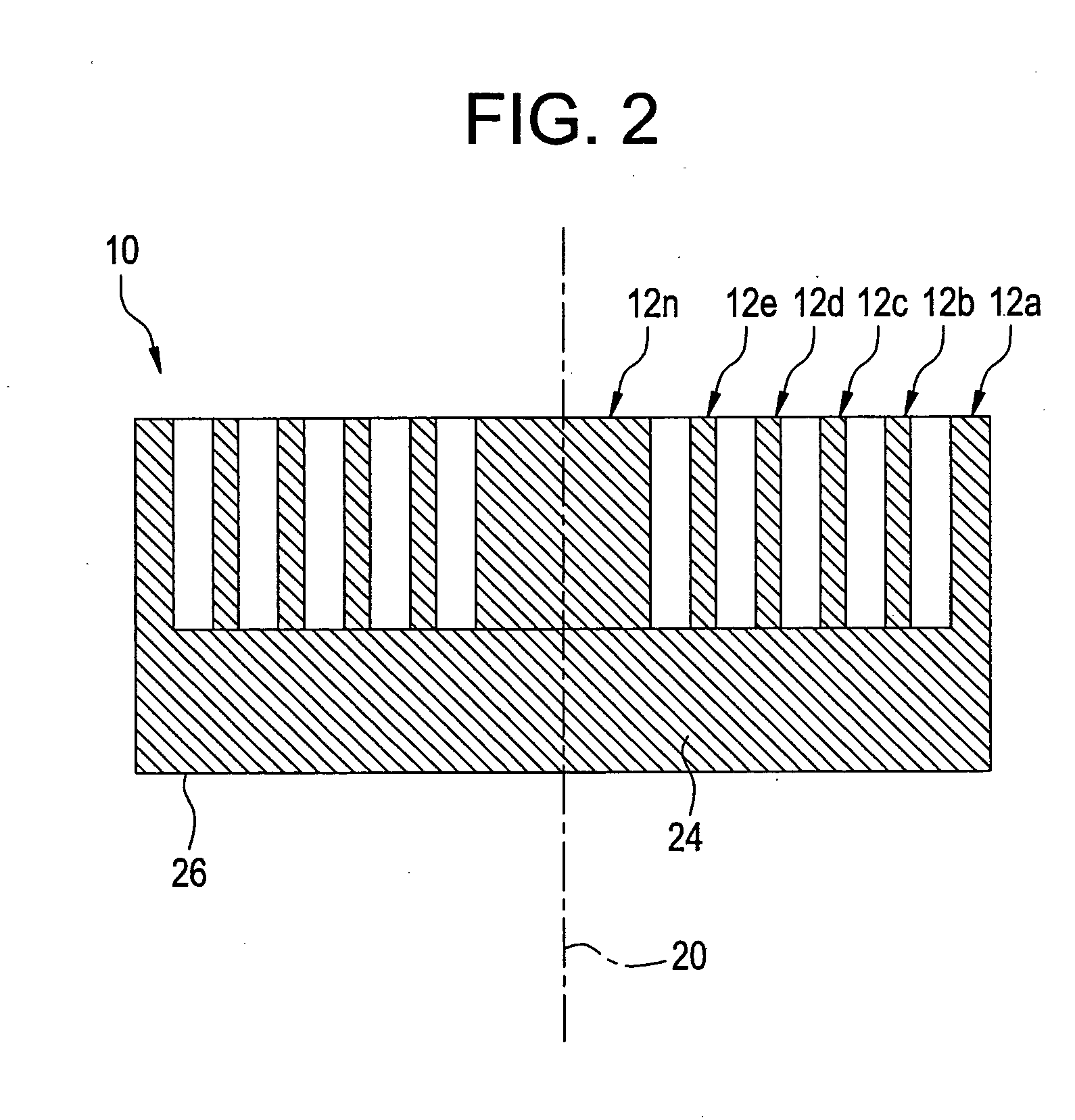
[0037] The electrochemical cell stack 10 described above has a number of advantageous features. For example, by increasing the number of electrochemical cells in a given stack the power packing density can be increased without any increase in the size (overall dimensions) of the stack 10. Thus by increasing the number of electrochemical cells in a stack from 1 to 2, the power packing density increases by about 84%, while increasing the number of electrochemical cells from 1 to 5 would cause an increase of about 116% in the power packing density. Similarly, a decrease in the spacing between successive electrochemical cells in the stack from 4 millimeters to 2 millimeters will cause an increase of about 30 to about 40% power generated for a stack of the same size. This method of stacking also increases the fuel utilization rate since the fuel is consumed rapidly by the presence of two similar reactive electrode surfaces bounding any channel within the stack through which the gas passes. The presence of two reactive surfaces increases the reaction probability.

Problems solved by technology

Both of these types of electrochemical cell designs suffer from several drawbacks, foremost amongst which is that these cells are generally incapable of generating a voltage greater than about 1 volt.
Tubular designs have the additional drawback of low volumetric power packing density.
One of the drawbacks of increasing the size (i.e., either the diameter or length) of an electrochemical cell to generate larger amounts of power is lower fuel utilization.

Method used


Image

  • Solid state electrochemical devices
  • Solid state electrochemical devices
  • Solid state electrochemical devices

Examples


example 1

[0039] In this paper example, the power as well as the volumetric power packing density for a stack having tubular electrochemical cells was studied as a function of the outer diameter of a tubular electrochemical cell. FIG. 3 is a graphical representation of the power as well as the volumetric power packing density (for a stack having tubular electrochemical cells) plotted versus the inner tube diameter. The electrochemical cells were arranged concentrically and the number of cells was increased from 1 to 3 to 5. The active length of the tube was 10 centimeters and the power density was 0.2 watts / square centimeter (W / cm.sup.2). The power generated as well as the volumetric power packing density for the electrochemical cells having 1, 3 and 5 cells respectively are shown in Tables 1, 2 and 3 respectively. The variation in the distance between successive tubes for the electrochemical cells having 3 and 5 electrochemical cells respectively are shown in Tables 2 and 3.

[0040] The result...

example 2

[0044] This paper example demonstrates how a high volumetric power packing density may be achieved in a fuel cell stack by stacking electrochemical cells in a manner such that with the exception of the outermost cell, each successive cell is placed within another cell. In this paper example, the volumetric power packing density in kW / L (kilowatt / unit length) generated by two different configurations of electrochemical cell stacks were compared. In one configuration, a single tubular electrochemical cell was used to determine the volumetric power packing density. In the other configuration, an electrochemical cell stack having 3 and 5 concentrically arranged electrochemical cells respectively were used to determine the volumetric power packing density. The volumetric power packing density (P.sub.v) developed in the cells was computed using the equation (I) below: 4 P v = 4 P an ( d 1 +n -1 2 d ) [ d 1 + ( n - 1 ) d ] 2 ( I )

[0045] where P.sub.a is the average power generated by the e...


PUM

PropertyMeasurementUnit
distanceaaaaaaaaaa
voltageaaaaaaaaaa
temperaturesaaaaaaaaaa

Abstract

In one embodiment, an electrochemical cell stack comprises at least two electrochemical cells, wherein each electrochemical cell comprises a hollow elongated electrolyte, having disposed upon it an anode and a cathode, and further wherein with the exception of the outermost cell, each electrochemical cell is placed within another electrochemical cell in a manner such that at least one of the surfaces of the respective electrochemical cells are approximately parallel to one another.

Description

[0001] This application claims the benefit of U.S. Provisional Application Ser. No. 60 / 461,580, filed Apr. 10, 2003.[0002] The present disclosure is related to solid state electrochemical devices.[0003] Solid state electrochemical devices such as fuel cells, oxygen pumps, sensors, and the like, generally offer opportunities for an efficient conversion of chemical energy to electric power with minimal pollution. Solid state electrochemical devices generally comprise an electrochemical cell, which is available in planar and tubular monolithic designs. Both of these types of electrochemical cell designs suffer from several drawbacks, foremost amongst which is that these cells are generally incapable of generating a voltage greater than about 1 volt. Tubular designs have the additional drawback of low volumetric power packing density. In other words, in order to generate an equivalent amount of power, a tubular electrochemical cell is generally much larger in size than a planar electroc...

Claims


Application Information

Patent Timeline
Patent Type & Authority Applications(United States)
IPC IPC(8): H01M4/86H01M4/88H01M4/90H01M4/92H01M8/02H01M8/10H01M8/12H01M8/24
CPCH01M4/8885H01M4/9016H01M4/9033H01M4/9066H01M8/0206H01M8/0215H01M8/0252H01M8/1246Y02E60/521Y02E60/525H01M4/8621Y02E60/50Y02P70/50
Inventor DU, YANHAISAMMES, NIGEL MARKENGLAND, RAYMOND OLIVER
Owner CONNECTICUT UNIV OF THE
Why Eureka
Try Eureka