Aerodynamic underbody device for trailer (and box-truck)

a trailer and underbody technology, applied in the field of trailer and underbody devices, can solve the problems of increasing the fuel consumption of the truck pulling the tractor-trailer, and none of the solutions offered have addressed the wind resistance of the undercarriage of the trailer, and achieve the effect of convenient installation

Inactive Publication Date: 2005-01-04
SCHWARTZ KARL JOHN
View PDF12 Cites 72 Cited by
  • Summary
  • Abstract
  • Description
  • Claims
  • Application Information

AI Technical Summary

Benefits of technology

Another object of the present invention is to provide a new and improved air drag reducing device that may be conveniently installed on existing trailers and box-trucks.

Problems solved by technology

The problem of increased fuel consumption of a truck pulling a tractor-trailer resulting from air resistance or drag at increased speed is well known.
None of the offered solutions has addressed the wind resistance from the undercarriage of the trailer including the coefficient of drag of the landing gear assembly and the ICC bumper permanently affixed to the trailer.

Method used


Image

  • Aerodynamic underbody device for trailer (and box-truck)
  • Aerodynamic underbody device for trailer (and box-truck)
  • Aerodynamic underbody device for trailer (and box-truck)

Examples


Embodiment Construction

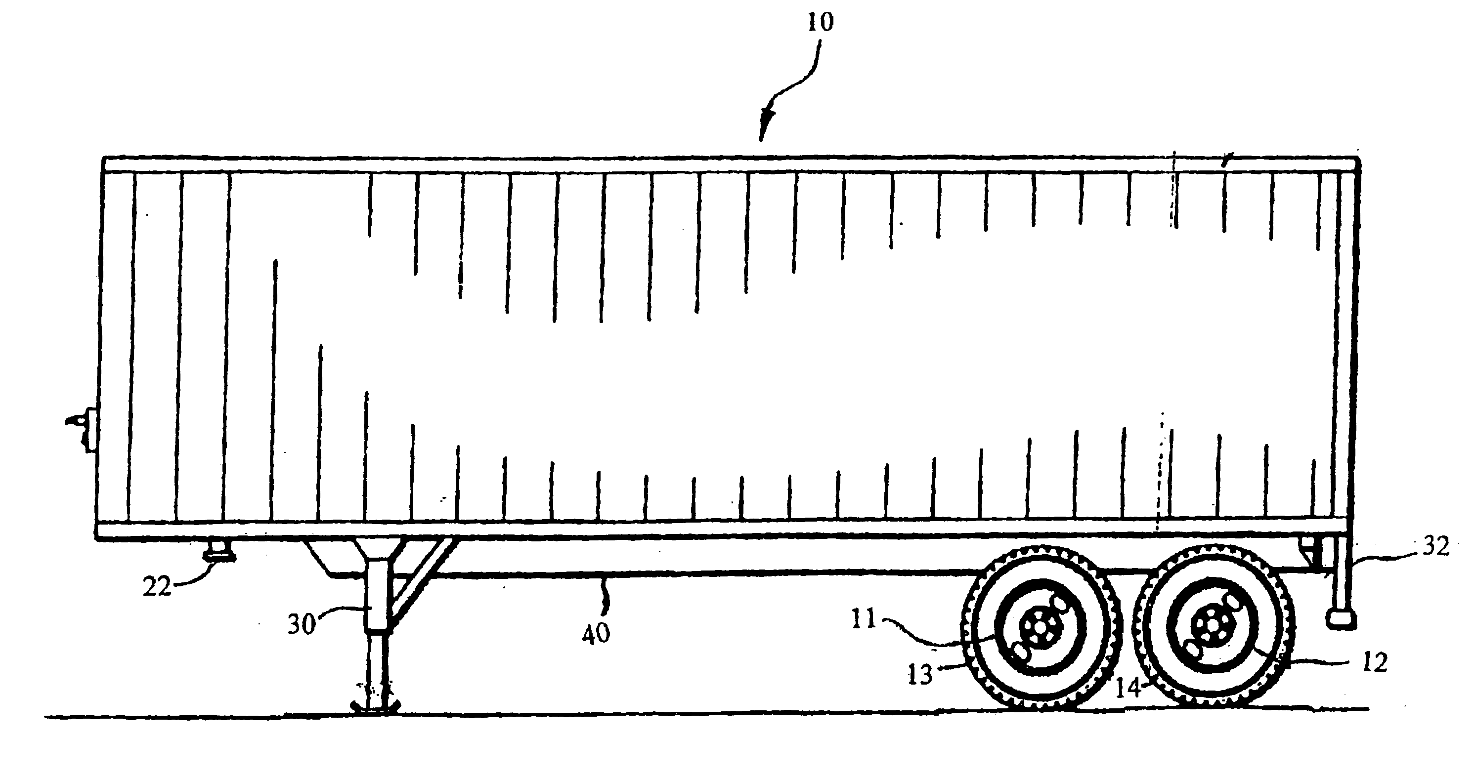
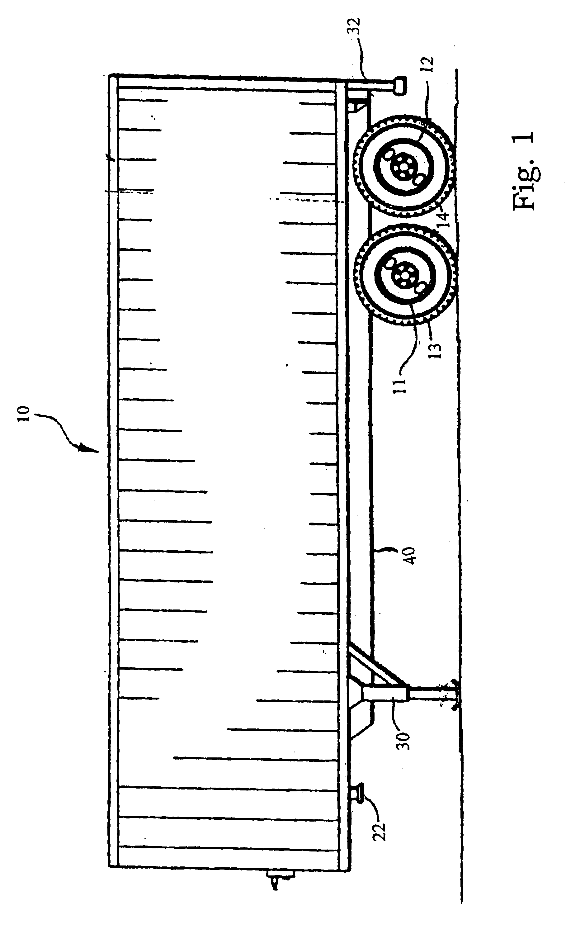
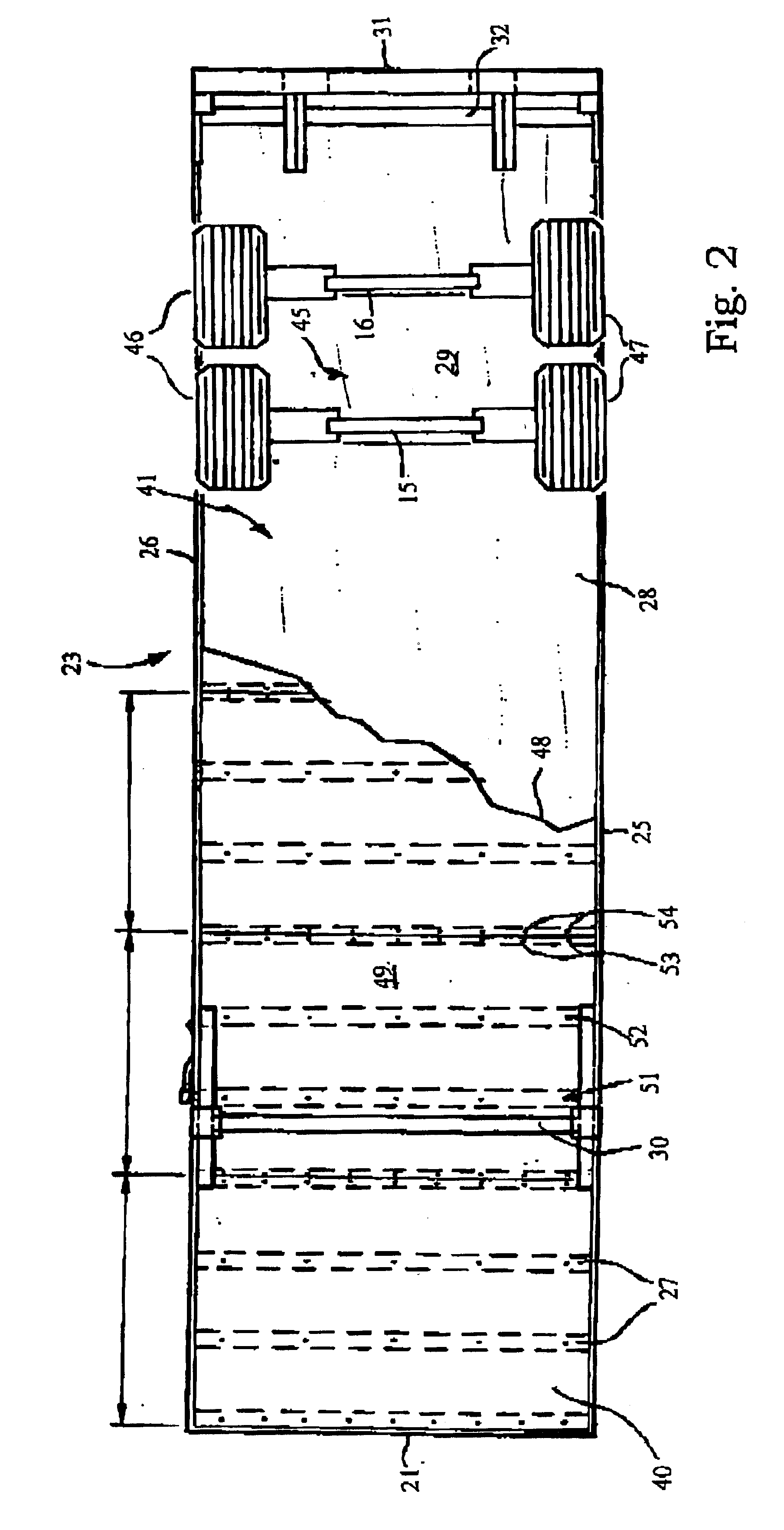
A typical elongated, eight wheel, double axel trailer 10 is shown diagrammatically in FIGS. 1 and 2, the trailer 10 having a two pairs of laterally spaced, rear wheels 11 and 12, with radial tires 13 and 14, the rear wheels having respective axles 15 and 16.

The trailer 10 is originally equipped with a metal front edge 21 and a truck / tractor hitch 22, and laterally spaced I-beams 27 forming the elongated undercarriage 23 with parallel side edges of a left side 25 and a right side 26, leaving the undercarriage 23 exposed to air traveling from the front edge 21 of the trailer 10 to the rear edge 31. The trailer 10 is equipped with a landing gear 30 located to the rear of the truck hitch 22 which is attached to the I-beams 27 and centered between left side 25 and right side 26. The trailer 10 is equipped with an ICC bumper 32 located in front of the rear edge 31 centered between left side 25 and right side 26.

As shown diagrammatically in FIG. 3, FIG. 3A and FIG. 3B, landing gear 30 is f...


PUM


Abstract

A belly pan, or membrane of rigid yet flexible material is of elongated shaped outline to be mounted along the bottom of tractor-trailer to improve the aerodynamic performance. The belly pan is provided with a tapered front portion to be attached to the frontal portion of the trailer to the approximate location of the truck hitch. The belly pan extends rearwardly, under the trailer, between the rear wheels in a rectangular portion and the rearward edge is affixed to the ICC bumper of the trailer. An aerodynamic shaped deflector is attached to the frontal portion of the landing gear of the trailer and attaches to the belly pan for reducing drag between the underside of the trailer and the support beams of the landing gear. A similar aerodynamic shaped deflector is attached to the frontal portion of the ICC bumper and attached to the belly pan for reducing drag between the underside of the trailer and the beams of the ICC bumper.

Description

CROSS-REFERENCE TO RELATED APPLICATIONNot ApplicableSTATEMENT REGARDING FEDERALLY SPONSORED RESEARCH OR DEVELOPMENTNot ApplicableREFERENCE TO SEQUENCE LISTINGNot ApplicableBACKGROUND OF THE INVENTIONThe present invention relates generally to the field of a device for improving the aerodynamic performance of a tractor-trailer thereby increasing fuel efficiency and more particularly to an underbody device for reducing wind or air resistance drag of the undercarriage of a trailer of a truck to enhance fuel economy.The problem of increased fuel consumption of a truck pulling a tractor-trailer resulting from air resistance or drag at increased speed is well known. The problem has been addressed in a number of ways or approaches by the prior art in reference to the combination of the truck and the trailer positioning, and the rear of the trailer. None of the offered solutions has addressed the wind resistance from the undercarriage of the trailer including the coefficient of drag of the l...

Claims


Application Information

Patent Timeline
Patent Type & Authority Patents(United States)
IPC IPC(8): B62D35/02B62D35/00
CPCB62D35/02Y02T10/88Y02T10/82
Inventor SCHWARTZ, KARL JOHN
Owner SCHWARTZ KARL JOHN
Why Eureka
Try Eureka