Water cool refrigeration

a technology of water cooling and condensers, which is applied in the direction of refrigeration components, refrigeration machines, stationary conduit assemblies, etc., can solve the problems of prolonging the life of compressors and power consumption, and achieve the effects of avoiding poor heat removal condensers, convenient installation, and saving installation costs

Active Publication Date: 2009-05-14
SZUTU HUI JEN
View PDF14 Cites 3 Cited by
  • Summary
  • Abstract
  • Description
  • Claims
  • Application Information

AI Technical Summary

Benefits of technology

[0006]The evaporative condenser of the present invention can be conveniently installed anywhere whether it is indoor or outdoor. Regardless of location, the evaporative condenser will eject all unwanted heat from a condensing coil to assure no heat will re-enter the refrigeration system to make the compressor pump the same heat over again.
[0007]One object of the invention is to provide a condensing unit of refrigeration and air-conditioning systems which do not need to be remotely installed outdoor. The evaporative condensers of the present invention can be installed anywhere in order to save on installation cost and to avoid poor heat removal condenser due to the improper location of a condensing unit. No heat will be re-pumped by a compressor significantly reducing power consumption and prolonging the life of a compressor.
[0008]Another object of the invention is to provide an evaporative condenser for the portable air-conditioning system where the hot refrigerant is cooled by water from a storage container, eliminating the flexible duct to vent hot air outside.
[0009]Another object of the invention is to provide an evaporative condenser which can last as long as the conventional refrigeration condenser. The hot refrigeration coil being cooled by water has the same effect as the refrigeration coil when submerged in water but without directly contacting the cooling water, preventing corrosion of the copper refrigeration tubing and the other metals make of the evaporative condenser.

Problems solved by technology

No heat will be re-pumped by a compressor significantly reducing power consumption and prolonging the life of a compressor.

Method used


Image

  • Water cool refrigeration
  • Water cool refrigeration
  • Water cool refrigeration

Examples


Embodiment Construction

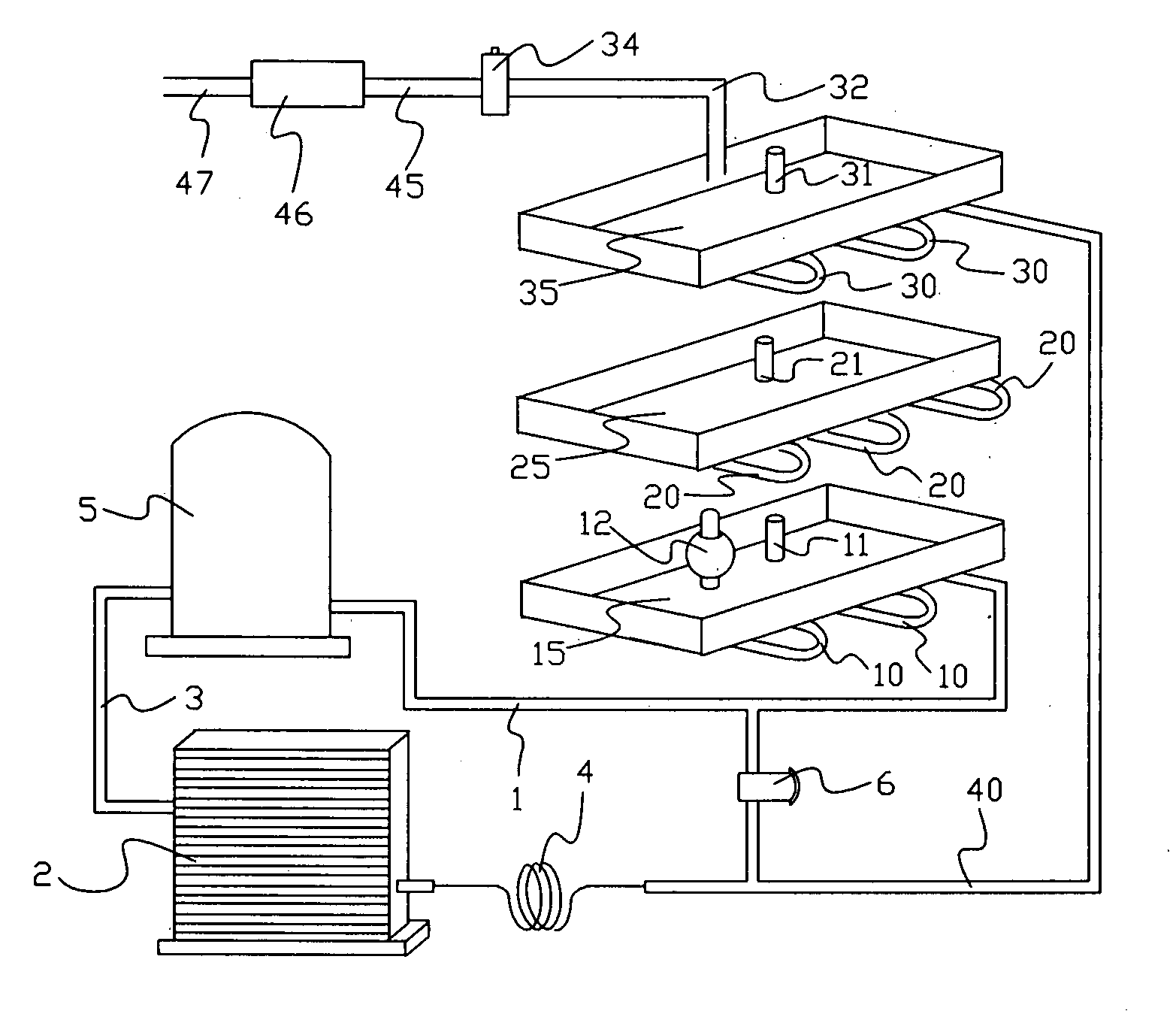
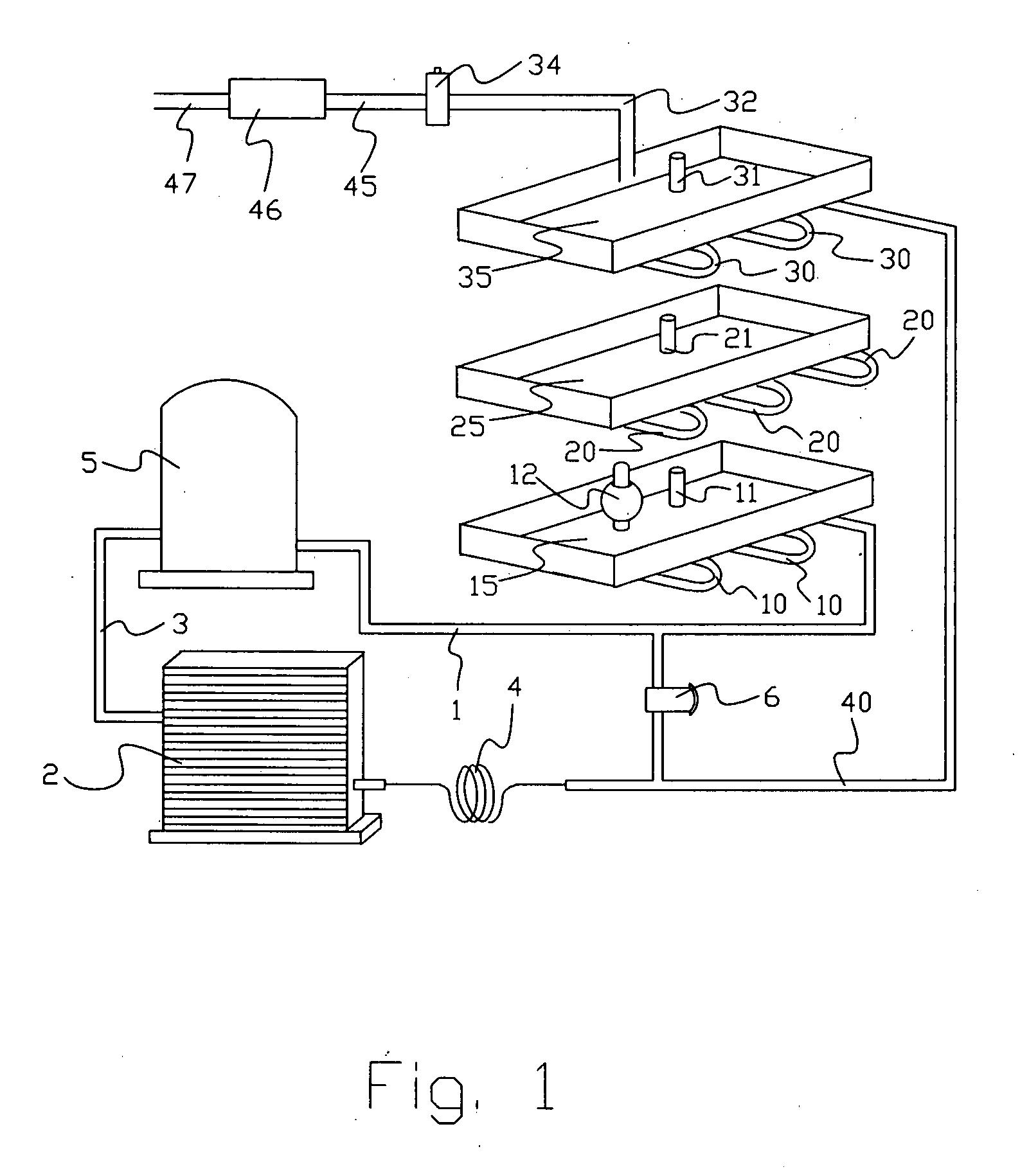
[0016]A compressor of a refrigeration system generates a lots of heat and all of this heat ideally needs to be ejected from the system before it goes back to the compressor for re-pumping. Referring to FIG. 1, and FIG. 4, the compressor 5 sucks refrigerant out from an evaporative coil 2, then the compressor 5 compresses the hot refrigerant to the condensing coil. The compressor discharge side 1 is piping the hot refrigerant to the first stage cooling coil 10 which is installed under the bottom water pan 15, then to the second stage cooling coil 20 which is installed under the middle water pan 25, and then to the final stage cooling coil 30 which is installed under the top water pan 35. The hot refrigerant ejects all the unwanted heat to the water in the water pans in different stages and the cooled refrigerant is piped to the input port 40 of the expansion valve 4. Due to the high efficiency of water cool, the refrigerant pressure may not be high enough for the expansion valve 4 to ...


PUM


Abstract

This invention is a water cooled refrigeration system which is equipped with an evaporative condenser comprising of multiple water pans with refrigeration coil soldered underneath for multi-stages cooling. The water pans are stacked on top of each other with the hottest coil located at the bottom. The bottom water pan dries up water faster than the other water pans since it has the hottest coil soldered underneath. Once the water level of the bottom water pan is low enough to be refilled, the supply water fills in from the top water pan and propagating downward to the water pan down below until it reaches the water pan at the bottom. The water refilling ceases once the bottom water pan is full. The unwanted heat from a refrigeration system is transferred from the refrigerant to the water, and then from the water to the air by evaporation.

Description

BACKGROUND OF THE INVENTION[0001]This invention relates to an evaporative condenser which is equipped to refrigeration or air-conditioning systems using water instead of air to cool the hot refrigeration coil by transferring heat from the hot refrigerant to the cooling water in multiple cooling stages. The water absorbs heat to make water vaporize into the air in a process known as evaporation, which is a natural physical phenomenon where water absorbs heat energy to change water from the liquid phase to vapor phase, resulting in a lower temperature. The beauty of this natural phenomenon is that the evaporation is able to lower the temperature of the said vapor departure spot below the ambient temperature. The temperature decrease is small, but provides a major advantage over air cooled since air cool condenser can never get lower than the ambient temperature.[0002]Evaporative condensers have an excellent cooling capacity, which translates into significant energy saving. For example...

Claims


Application Information

Patent Timeline
Patent Type & Authority Applications(United States)
IPC IPC(8): F28D5/00
CPCF25B39/04F28D5/00F25B2339/047F25B2339/041
Inventor SZUTU, HUI JEN
Owner SZUTU HUI JEN
Why Eureka
Try Eureka