Outdoor heater

a heater and outdoor technology, applied in the field of outdoor heaters, can solve the problems of time-consuming installation, low efficiency, and large and achieve the effect of convenient installation and small space in transportation and storag

Inactive Publication Date: 2015-09-10
JIANGSU GARDENSUN FURNACE
View PDF0 Cites 4 Cited by
  • Summary
  • Abstract
  • Description
  • Claims
  • Application Information

AI Technical Summary

Benefits of technology

[0008]The main object of the invention is to provide an outdoor heater which is convenient in installation and occupies small space in transportation and storage.

Problems solved by technology

Therefore, installation is time taking and efficiency is low.
Meanwhile, since a periphery of the reflect cover is usually bent downward, a big space will be need in transportation and storage.

Method used


Image

  • Outdoor heater
  • Outdoor heater
  • Outdoor heater

Examples


Embodiment Construction

[0029]A further detailed description will be given hereinafter with reference to the figures.

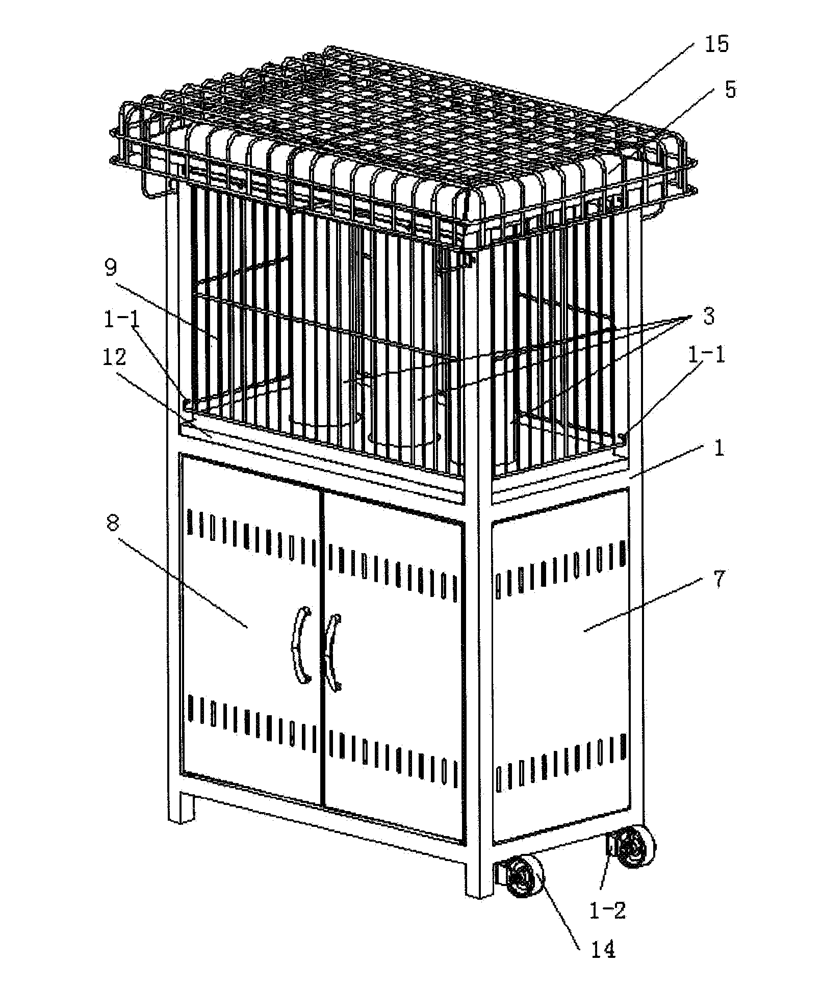
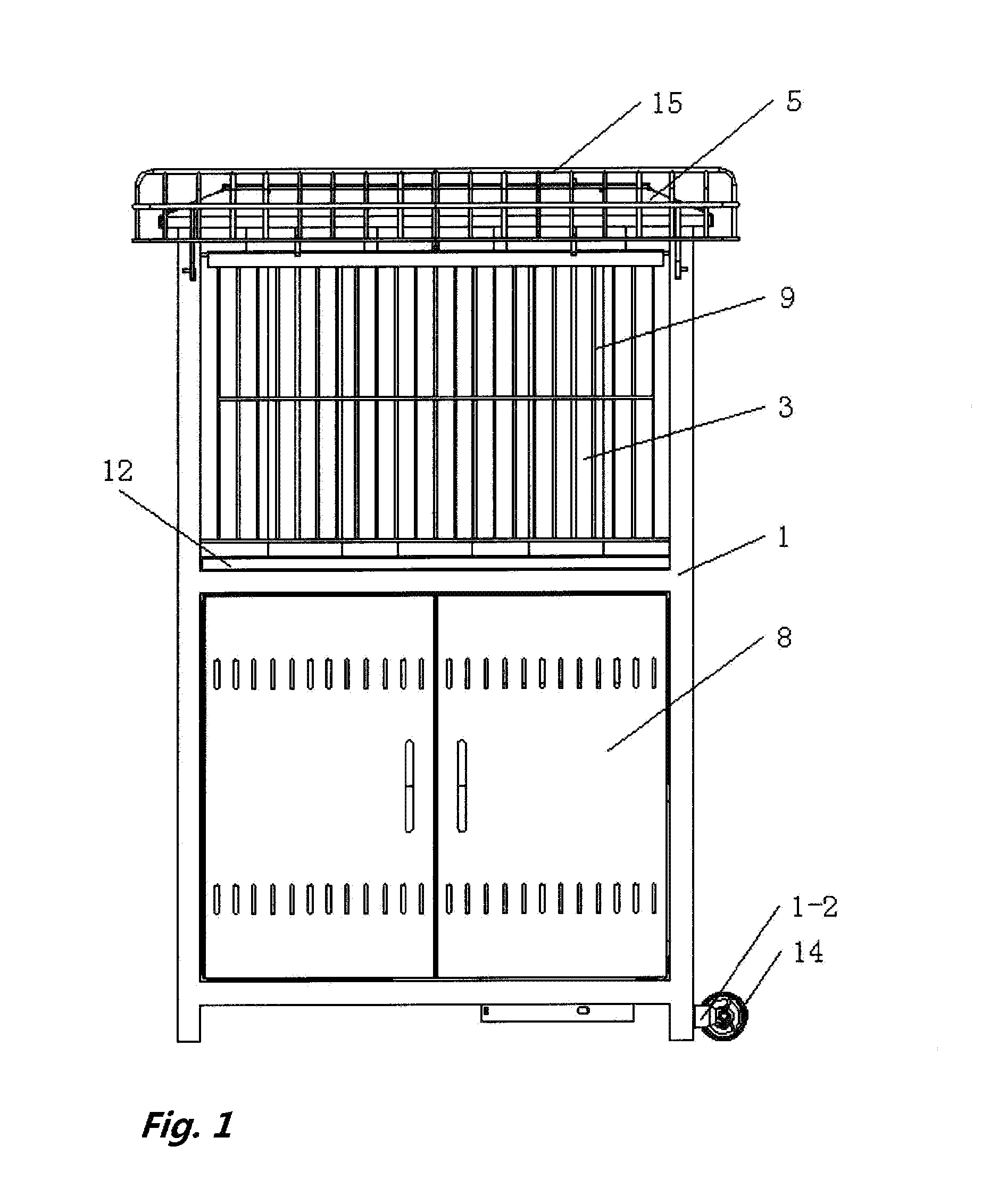
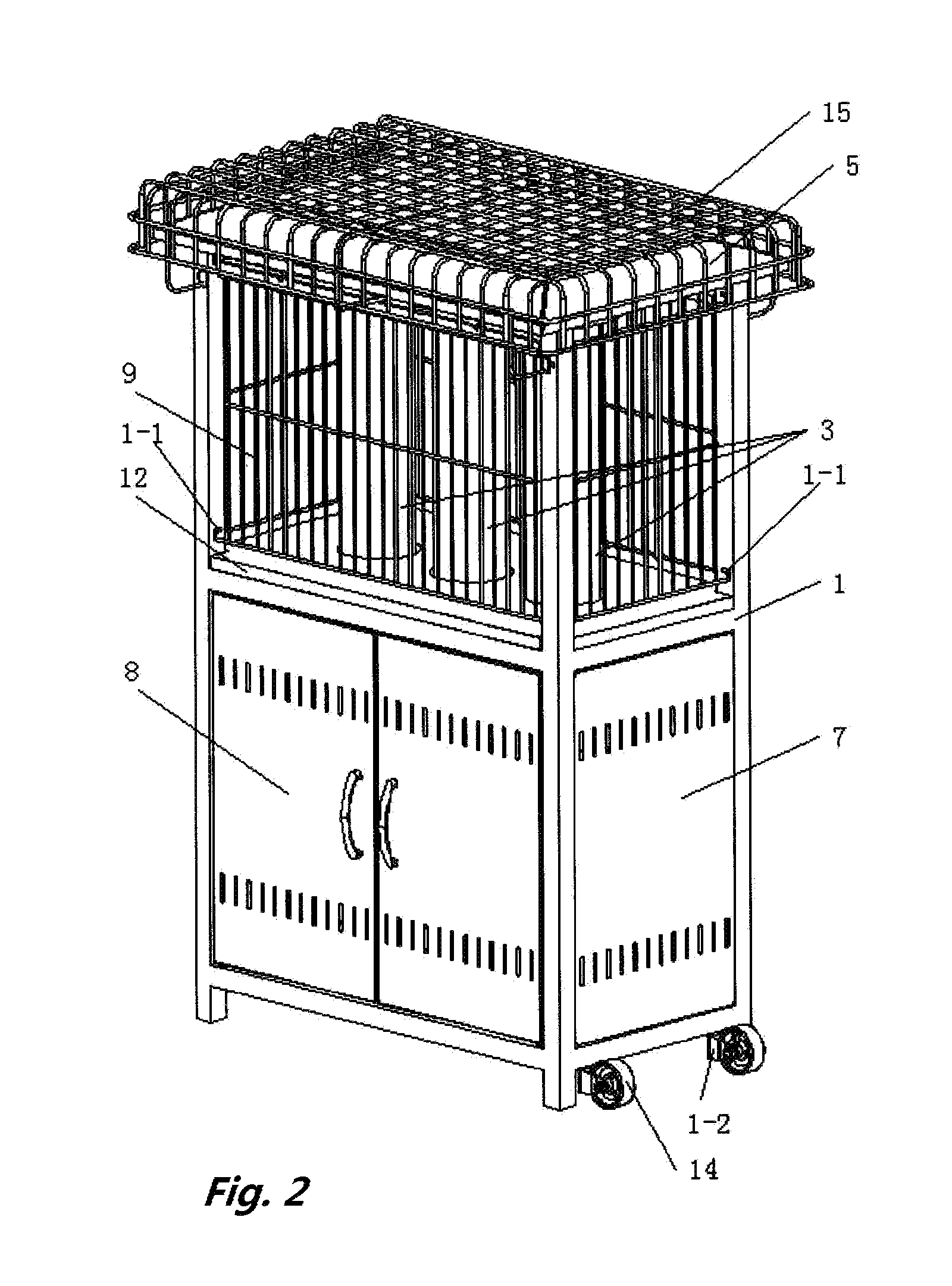
[0030]Wither reference to FIGS. 1 to 10, an outdoor heater has a frame 1, a control cabinet 2, a glass tube 3, an inflammation cover 4 and a reflect assembly 5. The frame 1 has a middle plate 6 having a through hole 6-1. The control cabinet 2 is below the middle plate 6 and has an inflammation assembly 10 contained therein right under the through hole 6-1 of the middle plate 6. The frame 1 has at least one door 8 installed on one side thereof and side panels 7 installed on the other sides thereof. A protective shield 9 is provided around an upper portion of the frame 1. The glass tubes 3 are placed on the through holes 6-1 of the middle plate 6. The inflammation cover 4 is placed on a top of the glass tubes 3. The reflect assembly 5 is above the glass tubes 3. The reflect assembly 5 has a central cover 5-1, top cover 5-2, and four separate side covers 5-3. The four separate side covers 5-3 a...


PUM


Abstract

An outdoor heater having a frame (1), a control cabinet (2), a glass tube (3), an inflammation cover (4) and a reflect assembly (5). The frame (1) has a middle plate (6) having a through hole (6-1). The control cabinet (2) is below the middle plate (6) and has an inflammation assembly (10) contained therein right under the through hole (6-1). The frame (1) has side panels (7) installed thereon. Protective shield (9) is provided around the frame (1). A linking pole (9-2) is respectively provided at each corner of the protective shield (9). The linking pole (9-2) is able to be inserted in “L” shaped installation holes (1-1) and be locked with respect to the frame (1) by, a first positioning plate (11).

Description

CROSS-REFERENCE TO RELATED APPLICATIONS[0001]Not ApplicableSTATEMENT REGARDING FEDERALLY SPONSORED RESEARCH OR DEVELOPMENT[0002]Not ApplicableINCORPORATION-BY-REFERENCE OF MATERIAL SUBMITTED ON A COMPACT DISC[0003]Not ApplicableBACKGROUND OF THE INVENTION[0004]1. Field of the Invention[0005]The invention relates to an outdoor heater.[0006]2. Description of Related Art[0007]Outdoor heaters are appliance placed out, of rooms for warming in winter from burning of gas. Conventional outdoor heaters have a frame, a control cabinet, an inflammation assembly, a glass tube, a reflect cover and a protective shield. The protective shield is usually fixed to the frame by screws or revit nuts. Therefore, installation is time taking and efficiency is low. Meanwhile, since a periphery of the reflect cover is usually bent downward, a big space will be need in transportation and storage.BRIEF SUMMARY OF THE INVENTION[0008]The main object of the invention is to provide an outdoor heater which is conv...

Claims


Application Information

Patent Timeline
Patent Type & Authority Applications(United States)
IPC IPC(8): F24H3/00F24D15/02F24H9/18F24H9/02
CPCF24H3/006F24H9/1881F24D15/02F24H9/02F24H1/06F24C3/022
Inventor WANG, JIANPINGWANG, JING
Owner JIANGSU GARDENSUN FURNACE
Why Eureka
Try Eureka