Fuel efficient dynamic air dam system

a dynamic air dam and fuel-efficient technology, applied in the direction of roofs, transportation and packaging, vehicle arrangements, etc., can solve the problems of no devices, inventions or methods, etc., and achieve the effect of improving vehicle fuel efficiency and maintaining safe handling characteristics

Inactive Publication Date: 2007-11-08
ANDERSON SCOTT
View PDF1 Cites 74 Cited by
  • Summary
  • Abstract
  • Description
  • Claims
  • Application Information

AI Technical Summary

Benefits of technology

[0008] It is the objective of the present invention to create a system that actively, dynamically, and in real-time adjusts the aerodynamics of a motor vehicle thus improving vehicle fuel efficiency while maintaining safe handling characteristics over a wide range of vehicle speeds, wind speeds, wind direction, and road surface conditions.
[0011] The pressure and temperature sensors are used to provide analog signals to the Aerodynamic Control Unit used by the software algorithms for measuring temperature and pressure and are placed at a plurality of locations on the vehicle. The pressure sensors combined with the current vehicle speed input provides a means for the Aerodynamic Control Unit software algorithms to determine how the air is flowing over under and around the vehicle and how it is affecting the vehicle's induced drag at any given speed. With this information the software algorithms can continuously adjust the positioning servos of active variable aerodynamic surfaces of the vehicle to achieve the best possible drag coefficient.
[0012] The proximity transducers are mounted along the fascia of the front air dam pointing down at a specific angle in the forward direction. These transducers provide a means for the Aerodynamic Control Unit and software to detect both road surface height as well as any approaching road debris. Using the input from the proximity transducers the Aerodynamic Control Unit and software algorithms maintain both an optimal air dam height over the road as well as detecting approaching road debris. By continuously adjusting the positioning servos of the active air dam the best possible drag coefficient is achieved. The Aerodynamic Control Unit will also retract the front air dam as needed when approaching road irregularities or debris. The Aerodynamic Control Unit software would also fully retract the front air dam at low vehicle speeds to prevent impact with objects such as raised parking curbs and road shoulders.
[0014] The servo motor amplifiers accept digital input signals from the Aerodynamic Control Unit software algorithms and in turn provide the analog output positioning signals used to control each of the positioning servos attached to the active aerodynamic vehicle surfaces. Position feedback is provided by encoders mounted to the position servos. Signals from the position servo encoders are used by circuits in the servo amplifiers to allow the amplifier to maintain constant control and accuracy over the position and velocity of movement for each active aerodynamic vehicle surface. This arrangement allows for a very fast positioning response to signals from the Aerodynamic Control Unit and software algorithms.
[0015] There are three primary aerodynamic surfaces which affect the aerodynamic characteristics of a motor vehicle. A front air dam is used to enhance aerodynamics and stability by varying the blocking of turbulent air flow under the vehicle chassis, side skirts are used to vary the blocking of turbulent air flow from the sides of the vehicle from entering under the vehicle chassis, and rear airfoils are used to help balance the pressure drag caused by differences between the top and bottom surface areas of the vehicle. Collectively these aerodynamic surfaces affect the overall drag caused by both induced and parasitic drag. By dynamically adjusting and varying these aerodynamic surfaces in direct response to actual air pressures, temperatures, and air densities, the air flow around, under and over a vehicle can be finely optimized at any given vehicle speed, wind speed or wind direction to minimize both induced and dynamic drag and to achieve the best possible overall drag coefficient.

Problems solved by technology

There are no devices, inventions or methods that are dynamically and automatically employed from the underside of a vehicle in order to improve fuel efficiency.

Method used


Image

  • Fuel efficient dynamic air dam system
  • Fuel efficient dynamic air dam system
  • Fuel efficient dynamic air dam system

Examples


Embodiment Construction

[0026] The terminology used herein should be interpreted in its broadest reasonable manner, even though it is being utilized in conjunction with a detailed description of a certain specific preferred embodiment of the present invention. This is further emphasized below with respect to some particular terms used herein. Any terminology that the reader should interpret in any restricted manner will be overtly and specifically defined as such in this specification. The preferred embodiment of the present invention will now be described with reference to the accompanying drawings, wherein like reference characters designate like or similar parts throughout.

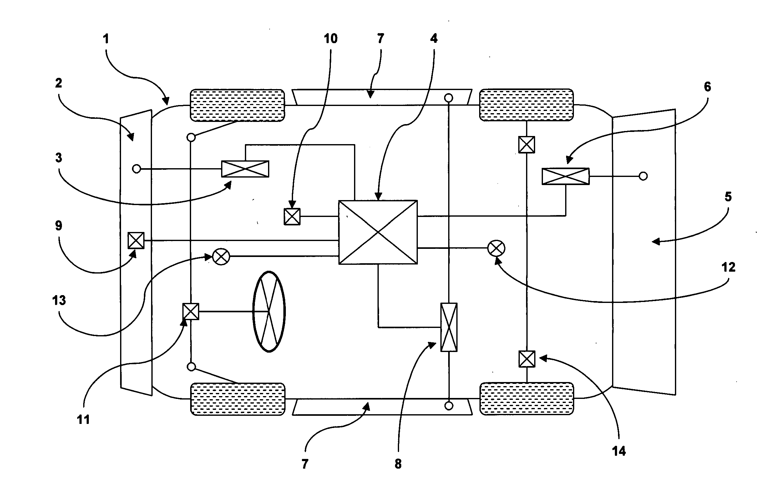
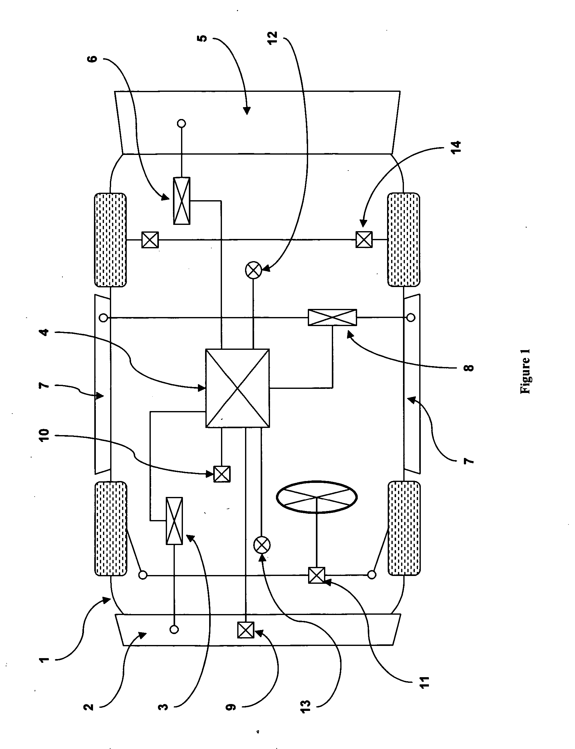
[0027] With initial reference to FIG. 1, an active microprocessor controlled aerodynamic system constructed in accordance with the teachings of the preferred embodiment of the present invention is generally identified with reference to the main Aerodynamic Control Unit identified with numeral 4. The Aerodynamic Control Unit 4 is show...


PUM


Abstract

Active, aerodynamic controller that describes a method for dynamically controlling airflow using computer controlled movable air dams and airfoils on motor vehicles. It is well known that motor vehicles generally have a great deal of aerodynamic friction also known as drag. Fuel efficiency is greatly affected by a vehicle's aerodynamic drag. Aerodynamic drag is caused by both induced drag and parasitic drag. Parasite drag is somewhat fixed by the overall design and shape of a vehicle. Parasite drag is caused primarily by the laminar flow of air over the smooth surfaces of the vehicle's hood, roof, windows, side mirrors and door panels. Induced drag is much more variable and is primarily created by the differential pressure effects of air flowing over, under and around a vehicle, as well as the relative airflow caused by both ground effect and atmospheric air density and wind. This invention serves to actively minimize the effects of induced drag thus reducing the amount of fuel used by vehicles fitted with this invention.

Description

BACKGROUND OF THE INVENTION [0001] 1. Technical Field [0002] The present invention generally relates to motor vehicles and aerodynamic drag. More particularly, the present invention relates to a microcomputer controlled aerodynamic management system for motor vehicles that controls a plurality of movable aerodynamic surfaces (sometimes referred to as air dams and foils). The present invention also addresses the direct and active management of induced air drag as it relates to varying speeds and environmental conditions, such as road and wind conditions, encountered by motor vehicles during travel. [0003] 2. Description [0004] The fuel economy of a motor vehicle is significantly affected by induced drag. Induced drag is created primarily by the difference in air pressure between the top and bottom of a vehicle. As a result, vehicle fuel efficiencies are directly affected by vehicle speed, air densities, ground features, wind and wind direction. [0005] Many of today's vehicle designs ...

Claims


Application Information

Patent Timeline
Patent Type & Authority Applications(United States)
IPC IPC(8): B62D35/00
CPCB62D35/00Y02T10/88
Inventor ANDERSON, SCOTT
Owner ANDERSON SCOTT
Why Eureka
Try Eureka