Load-lifting apparatus and method of storing energy for the same

a technology of load-lifting apparatus and energy storage, which is applied in the direction of motor/generator/converter stopper, dynamo-electric converter control, elevator, etc., can solve the problems of reducing overall fuel efficiency, reducing fuel efficiency, and oversized diesel engines. , to achieve the effect of reducing noxious prime power emissions, increasing fuel efficiency, and operating quietly

Active Publication Date: 2009-06-30
MI JACK CANADA
View PDF15 Cites 74 Cited by
  • Summary
  • Abstract
  • Description
  • Claims
  • Application Information

AI Technical Summary

Benefits of technology

[0032]The principal advantages of this invention are substantial increased fuel efficiency and lower noxious prime power emissions. In an energy storage dominant configuration, the hybrid RTG crane can be operated on stored power alone and so can be operated quietly and without any noxious emissions inside confined quarters. The components of the hybrid power system can be distributed at different convenient locations on the gantry or crane structure so as to provide enhanced stability as well as ease of service. Furthermore, the power system architecture of the present invention allows a reduction in the size of the generator used to power the crane or load-lifting apparatus, as the energy storage system helps alleviate the power rating requirement of the prime power source with respect to the peak power requirement for lifting a load.

Problems solved by technology

The diesel engine is typically oversized to provide peak power bursts and prevent excessive voltage drop when lifting.
These engines are typically run at constant speed for frequency control and so are not maximized for fuel efficiency.
In typical service, the RTG crane has a duty cycle with a high idle content which reduces overall fuel efficiency and increases unwanted emissions.
These are (1) the restriction on the freedom of placement that all power components and (2) operations that inevitably result in engine-torque jumps and transient operating states that are determinative for the toxic constituents contained in the exhaust gas.
Further, the mobile crane of U.S. Pat. No. 6,688,481 does not include a regenerative braking capability and so does not maximize fuel efficiency.
However, the battery is not directly connected to the DC power bus of the system and requires a charge control element, while being restricted to AC motors.
However, these documents state that, according to their knowledge, the battery component imposes numerous problems such as: small electrical capacity, electrical inefficiency, large physical battery volume, heavy weight, and short battery life, whereby such a system is not currently a viable way to accomplish energy storage utilizing even state-of-the-art battery technology.

Method used


Image

  • Load-lifting apparatus and method of storing energy for the same
  • Load-lifting apparatus and method of storing energy for the same
  • Load-lifting apparatus and method of storing energy for the same

Examples


Embodiment Construction

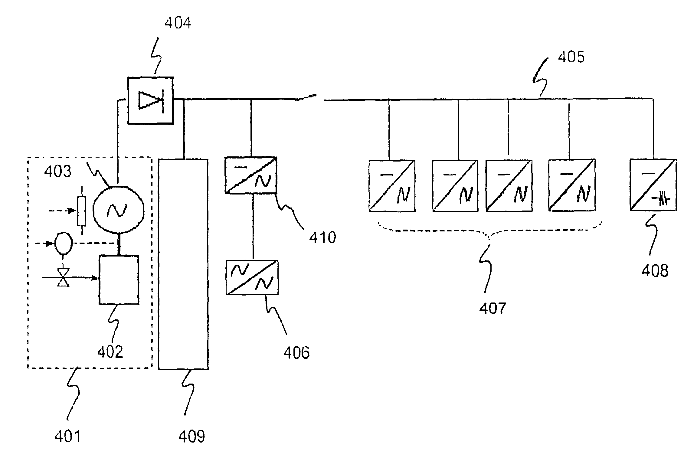
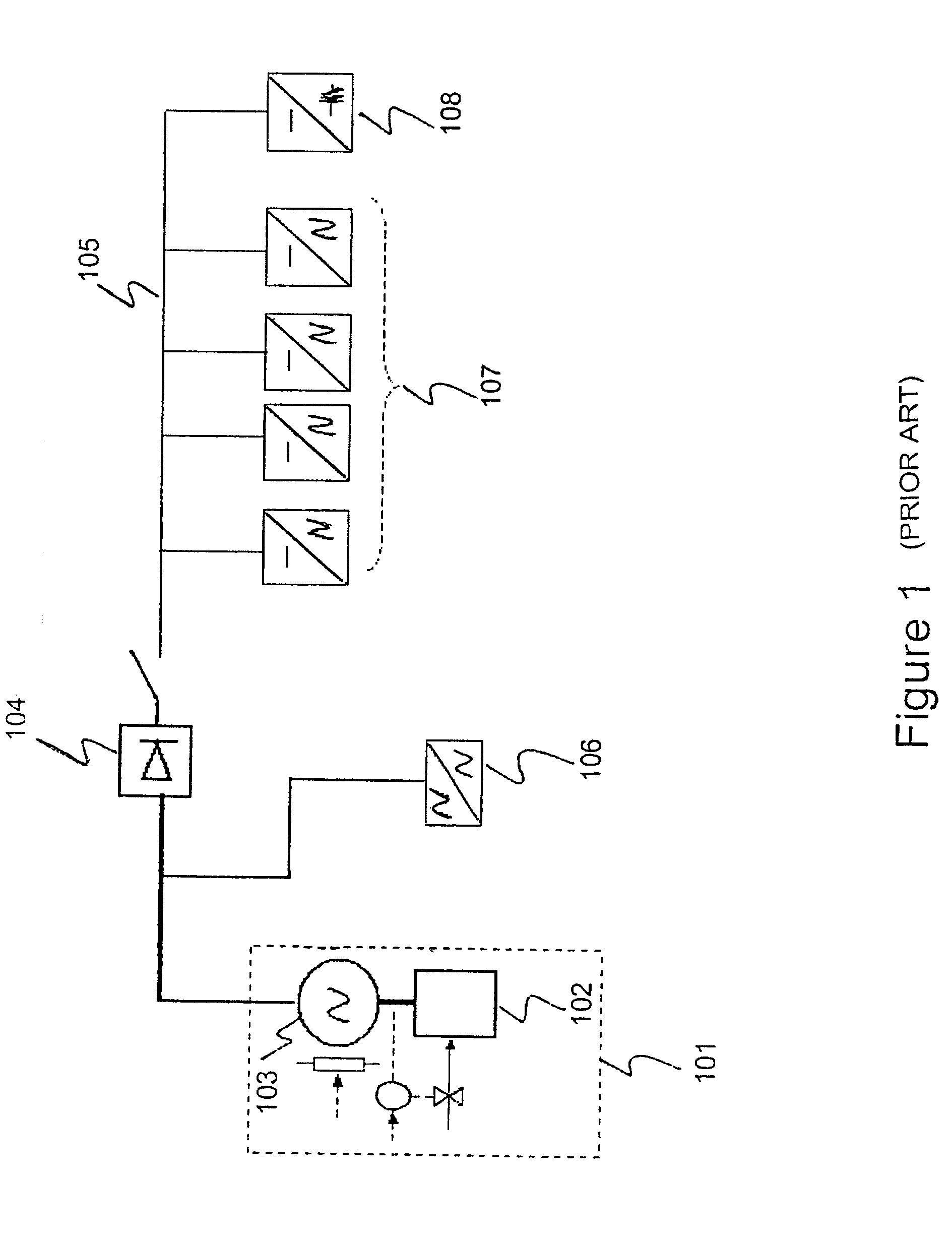
[0064]FIG. 1 is a prior art schematic of a rubber-tired gantry crane power system. Prime power is provided by a diesel genset 101 which is comprised of a diesel engine 102 and an alternator 103 which converts mechanical power from the engine 102 to AC electrical power. AC power is available for the crane's auxiliary power systems 106 and is converted by rectifier 104 to DC power supplied to a DC bus 105 for distribution to operate electric motors 107 for propelling the crane and to carry out other crane operations such as traversing and, lifting and lowering. The crane may also have a dynamic brake capability 108 which allows the motors 107 to act as electrical generators providing a braking force while lowering a load. The electrical energy generated by the dynamic braking system 108 is typically dissipated in a resistive grid (not shown).

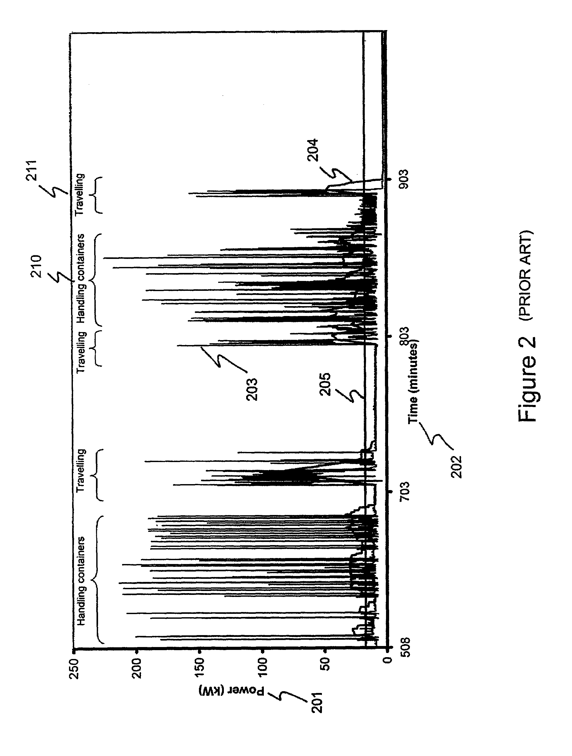
[0065]FIG. 2 is a graph showing a typical duty cycle of a prior art rubber-tired gantry crane. FIG. 2 shows power 201 versus time 202 for a porti...


PUM


Abstract

A load-lifting apparatus has one or more prime power sources, one or more energy storage systems and regenerative braking. Regenerative energy is recovered when the load-lifting apparatus lowers its load. The elements of the prime power sources, energy storage devices and electrical components may be distributed to provide stability for the load-lifting apparatus. The general power architecture and energy recovery method can be applied to cranes, rubber-tired gantry cranes, overhead cranes, mobile cranes, ship-to-shore cranes, container cranes, rail-mounted gantry cranes, straddle carrier cranes and elevators. In such an architecture, the energy storage system helps alleviate the power rating requirement of the prime power source with respect to the peak power requirement for lifting a load.

Description

CROSS REFERENCE TO RELATED APPLICATION[0001]The present application claims the benefits, under 35 U.S.C. §119(e), of U.S. Provisional Application 60 / 804,614 entitled “Hybrid Gantry Crane” filed Jun. 13, 2006, which is incorporated herein by reference.FIELD OF THE INVENTION[0002]The present invention relates generally to the design of a load-lifting apparatus. More particularly, the present invention relates to a load-lifting apparatus comprising one or more prime power sources, one or more energy storage systems and a means of regenerative braking. The general power architecture and energy recovery method can be applied to elevators. The invention also relates to a method for storing energy for a load-lifting apparatus.BACKGROUND OF THE INVENTION[0003]Rubber-Tired Gantry (“RTG”) cranes are widely used in port facilities to move cargo, especially large cargo containers. These cranes typically can lift and transport loads weighing in the range of about 10,000 kilograms to about 50,000...

Claims


Application Information

Patent Timeline
Patent Type & Authority Patents(United States)
IPC IPC(8): H02P3/00
CPCB66C13/18B66C13/28B66C19/007Y02T30/00
Inventor WEGNER-DONNELLY, FRANKCOUSINEAU, RAYMONDMAI, SERGE
Owner MI JACK CANADA
Why Eureka
Try Eureka