Transformer-free waveguide circulator

a waveguide and transformer-free technology, applied in waveguide devices, basic electric elements, electrical apparatus, etc., can solve the problems of significant impact on the size, mass, and loss of the device, and achieve the effect of reducing the loss, reducing the loss, and eliminating the additional size and mass

Inactive Publication Date: 2007-07-10
EMS TECHNOLOGIES
View PDF19 Cites 25 Cited by
  • Summary
  • Abstract
  • Description
  • Claims
  • Application Information

AI Technical Summary

Benefits of technology

[0009]Briefly stated, the present invention is a waveguide circulator that eliminates the need for additional impedance matching circuitry or elements to provide a broadband impedance match between ferrite elements and an air-filled waveguide. The waveguide circulator in accordance with the invention eliminates the need for additional parts or features and thus reduces insertion loss, size, and mass. Specifically, this invention eliminates the loss associated with quarter-wavelength dielectric transformer sections and the adhesive used in the assembly of such, and eliminates the additional size and mass required for the dielectric or air-filled waveguide transitional sections. The lower parts count also results in a savings of time and parts cost. Furthermore, it will be seen that the frequency bandwidth of the present invention is comparable to, if not broader than, that of the present art, with one exemplary prototype yielding a bandwidth of over 20% at the 21 dB isolation point and another exemplary prototype yielding a bandwidth of over 40% at the 14 dB isolation point, both at K-band. The percent bandwidth is defined as 100 times the frequency span for which a minimum requirement, such as 21 dB of isolation, is met, and divided by the average of the minimum and maximum frequency values for which the requirement is met.
[0010]In an illustrative form, the present invention comprises an improved waveguide circulator that eliminates the need for quarter-wave dielectric transformers or impedance steps in the interface waveguide for broadband operation. The illustrative embodiment employs a relatively tall, relatively thin ferrite element having a high saturation magnetization value to achieve good, broadband circulator performance without the addition of impedance matching elements in order to minimize the size, mass, and loss of the circulator.
[0012]Preferably, the ferrite element is Y-shaped with its protruding parts being referred to as “legs”, although persons skilled in this art will recognize that other shapes can be utilized as desired. Also, the circulator can be combined with other such circulators in a larger switch or other device. Because the circulator can be constructed without the dielectric transformers, the individual circulators can be significantly smaller, lighter, and less costly. When a number of these smaller, lighter, less costly circulators are integrated together in a larger device, the savings in size, weight, and cost can be substantial.
[0015]Thus, it is an aspect of the invention to provide a single junction broadband ferrite circulator that eliminates additional matching sections such as quarter-wave dielectric transformers or steps in the height or width of the waveguide structure while achieving either an isolation of at least 21 dB over a frequency bandwidth of at least 5% or an isolation of at least 14 dB over a frequency bandwidth of at least 20%.

Problems solved by technology

Additionally, the internal transitions between ferrite elements do not include any quarter wavelength transformer sections, which would significantly impact the size, mass, and loss of the device.

Method used


Image

  • Transformer-free waveguide circulator
  • Transformer-free waveguide circulator
  • Transformer-free waveguide circulator

Examples


first embodiment

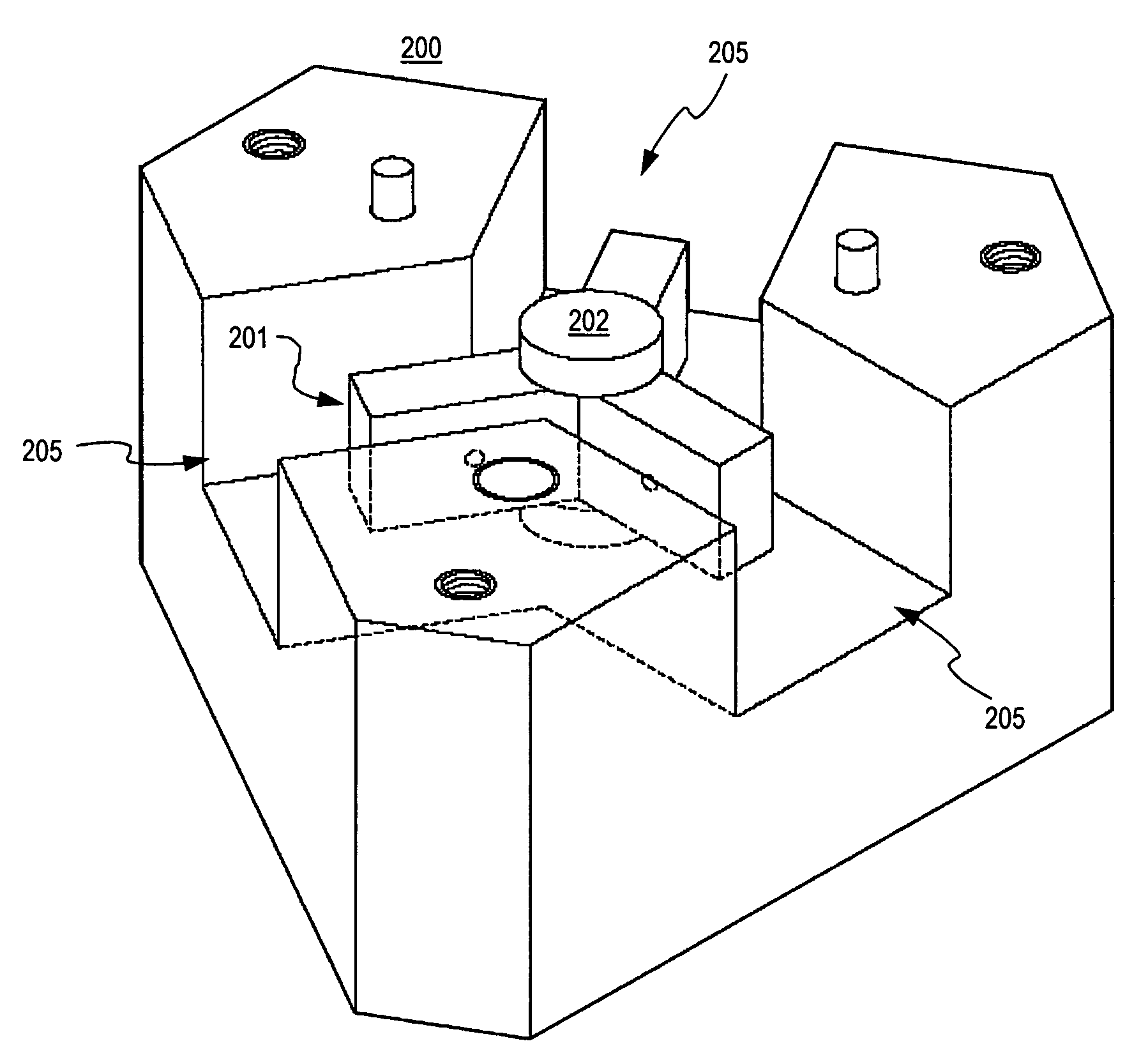
[0029]FIG. 3 shows a top view, and FIG. 7 shows an isometric view, of a multi-junction waveguide circulator 200 in accordance with the invention. It is similar in concept and description to the circulator of FIG. 1, but the quarter-wave dielectric transformer sections are not present. Additionally, there are no steps in the height or width of the waveguide structure. FIGS. 3 and 7 show a ferrite element 201 with a dielectric spacer 202 disposed on its top surface. Generally, a second dielectric spacer would be used, located underneath the ferrite element, hidden in FIG. 3 and shown in phantom in FIG. 7 The ferrite element 201 and dielectric spacers 202 are disposed within the conductive waveguide structure 200. The conductive waveguide structure 200 also includes three waveguide input / output ports 205. Although empirical matching elements are not shown, they may be disposed on the surface of the conductive waveguide structure as in the prior art. It is important to the note that whi...

second embodiment

[0033]FIG. 6 shows a top view of a multi-junction waveguide circulator in accordance with the invention. This circulator configuration is referred to as a single pole, four throw switch network (SP4T). An SP4T switch is comprised of three switching circulators and also referred to as a multi-junction circulator with three ferrite junctions. It is important to note that while the described embodiments illustrate the ferrite element as having a Y-shape with three legs, the invention can also include use of ferrite elements having a variety of differing shapes, including a triangular puck. While these shapes may not be considered to have legs or protruding portions as described above, they nevertheless have a particularly protruding portion which may operate in a manner similar to the toroid legs described above.

[0034]FIG. 6 shows a conductive waveguide structure 340 that includes three ferrite elements (also called toroids) 302, 304, and 306 configured in a manner so that at least one...


PUM


Abstract

An improved waveguide circulator that eliminates the need for quarter-wave dielectric transformers or impedance steps in the interface waveguide for broadband operation is described. The circulator designs in the prior art all require impedance matching elements outside of the ferrite element in order to achieve acceptable performance. Through the use of this new invention, broadband circulator performance can be achieved without the addition of impedance matching elements in order to minimize the cost, size, mass, and loss of the circulator.

Description

CROSS REFERENCE TO RELATED APPLICATION[0001]The present application claims the priority benefit of U.S. provisional patent application Ser. No. 60 / 348,194 filed Nov. 7, 2001, U.S. non-provisional patent application Ser. No. 10 / 289,460 filed Nov. 7, 2002, and U.S. provisional patent application Ser. No. 60 / 554,316, filed Mar. 18, 2004, and incorporates the same herein by reference.BACKGROUND OF THE INVENTION[0002]1. Field of the Invention[0003]The invention relates in general to waveguide circulators for the non-reciprocal transmission of microwave energy; and more particularly to a novel approach for reducing the size, insertion loss, and cost of a waveguide switching circulator.[0004]2. Description of the Related Art[0005]Ferrite circulators have a wide variety of uses in commercial and military, space and terrestrial, and low and high power applications. A waveguide circulator may be implemented in a variety of applications, including but not limited to low noise amplifier (LNA) r...

Claims


Application Information

Patent Timeline
Patent Type & Authority Patents(United States)
IPC IPC(8): H01P1/38H01P1/39
CPCH01P1/39
Inventor KROENING, ADAM M.
Owner EMS TECHNOLOGIES
Why Eureka
Try Eureka