

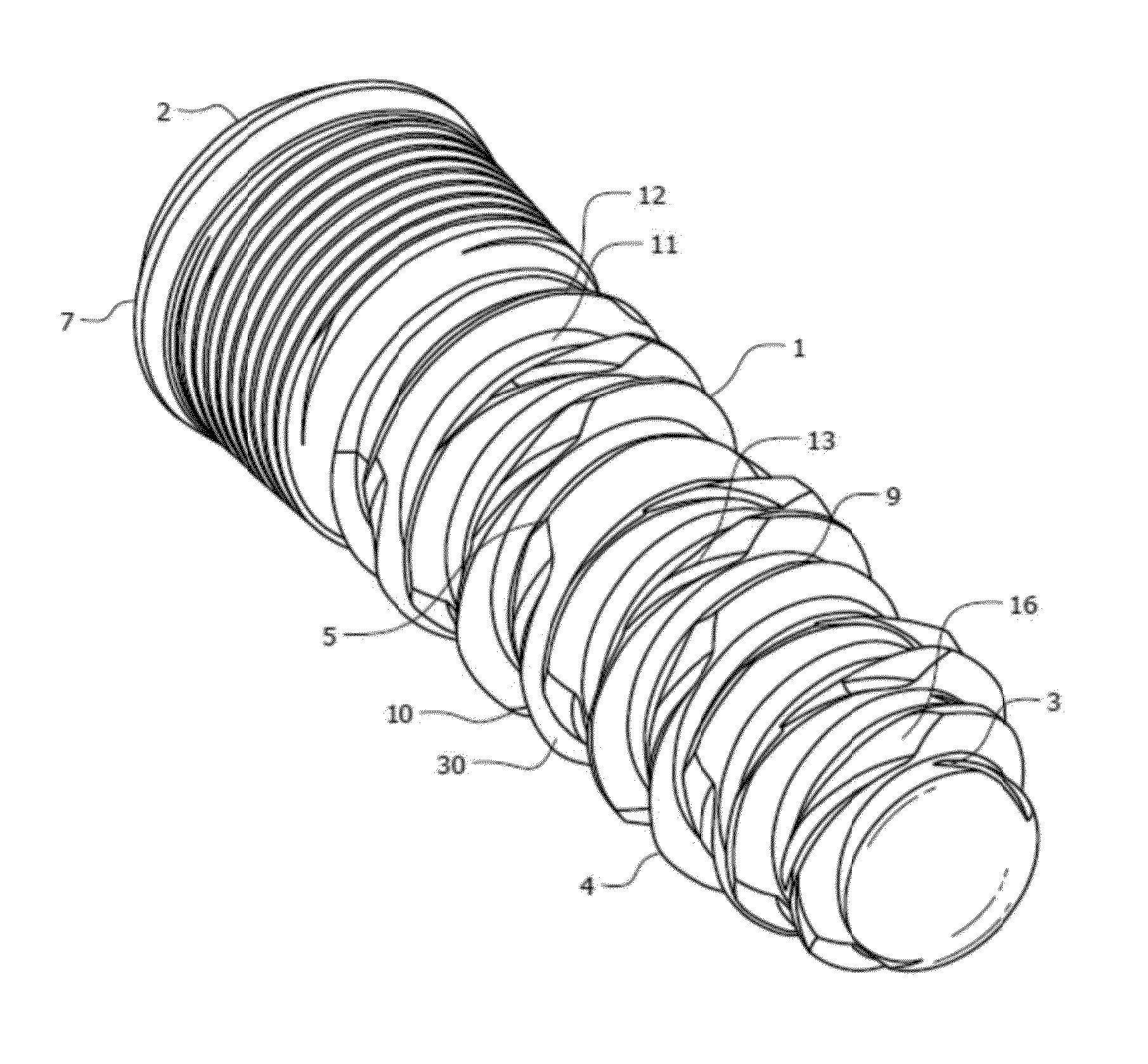
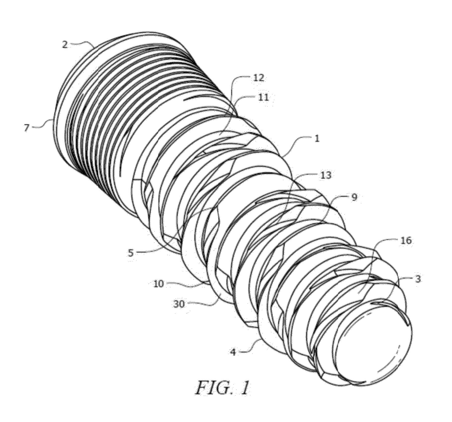
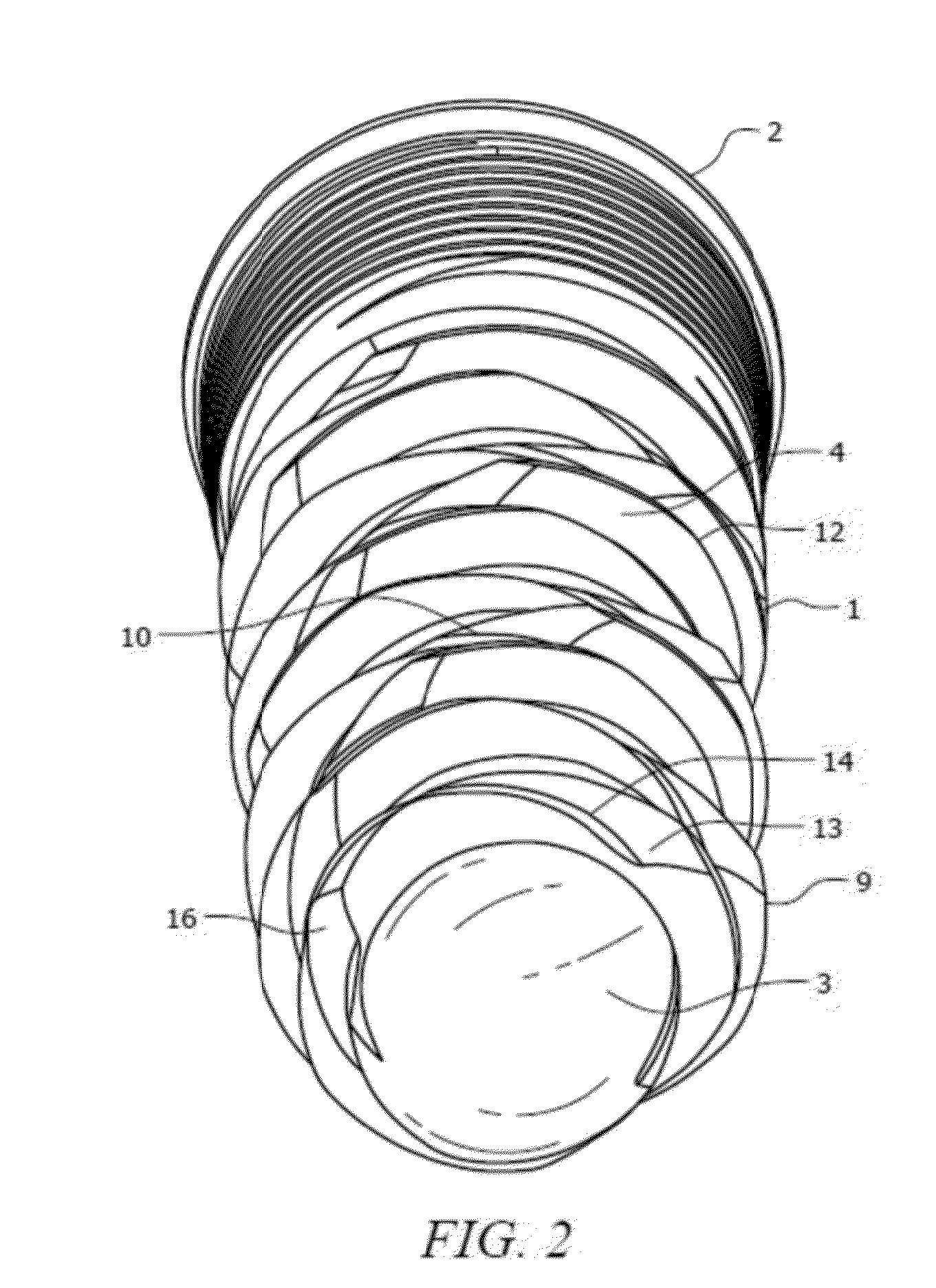
Dental Implant and Method for Rapid Integration
a dental implant and rapid integration technology, applied in the field of bone implants, can solve the problems of micromotion, weakening and potential failure of implants, and limited thread cutting ability of present devices, and achieve the effect of reducing micromotion
- Summary
- Abstract
- Description
- Claims
- Application Information
AI Technical Summary
Benefits of technology
Problems solved by technology
Method used
Image

Examples
example 10
[0101]Laboratory In Vivo Model
[0102]Implants of the following invention along with a control implant were inserted into the mandible of sheep. Pilot holes equal to diameter of the shaft of the implant were drilled and the implants inserted with a handpiece.
[0103]Histological Analyses and MicroCT Imaging.
[0104]Mandible sections were removed and 3 and 6 week intervals. The samples were fixed in 10% phosphate buffered formalin for 24 hours and then gradually dehydrated in a series of alcohol concentrations (70% Ethanol for 24 hrs, 95% Ethanol for 24 hrs, 100% Ethanol (×2) 48 hrs). After dehydration, the samples were infiltrated and embedded in autopolymerizing methyl metacrylate resin. Upon the completion of the curing process the embedded blocks were scanned by means of microCT scan (μCT 40 Scanco Medical, Brüttisellen, Switzerland) to generate microCT images. The microCT with a small-angle cone beam operating at room temperature was set at 70 kV, anode current of 114 μA, and a...
PUM
 Abstract
Description
Claims
Application Information