Apparatus for controlling speed of mobile object

a technology for controlling the speed of objects and vehicles, applied in the direction of non-deflectible wheel steering, navigation instruments, external condition input parameters, etc., can solve the problems of occupants being uncomfortable and/or afraid, the speed of the controlled vehicle is too fast, and the occupants may feel uncomfortable and/or fear, so as to facilitate the control of the speed feeling of the driver and reduce the effect of the driver

Active Publication Date: 2012-02-23
DENSO CORP
View PDF11 Cites 57 Cited by
  • Summary
  • Abstract
  • Description
  • Claims
  • Application Information

AI Technical Summary

Benefits of technology

[0010]Specifically, a further aspect of the present disclosure aims to provide such apparatuses for reducing an occupant of the mobile object from feeling uncomfortable or fear in controlling a speed of the mobile object.
[0012]The inventors of the present disclosure have discovered that each component of divergence is tightly associated with the driver's sense of speed. That is, the components of divergence are increased with increase in the speed of the vehicle, and reduced with reduction in the speed of the vehicle. In addition, each component of divergence as one factor of the relative flow of the environmental field is characterized to increase with reduction in the distance with respect to the mobile object and to decrease with increase in the distance with respect to the mobile object.
[0015]The aspect of the present disclosure allows the speed feeling of the driver to be specifically grasped. This makes it possible to easily control the speed feeling of the driver to reduce the driver from feeling uncomfortable or fear due to the driver's speed feeling.

Problems solved by technology

However, if the controlled vehicle runs on a curve road at the same speed as that on a straight road, occupants of the controlled vehicle may feel that the speed of the controlled vehicle is too fast.
This may result in that the occupants feel uncomfortable and / or fear.
In the related arts, because it is difficult to grasp speed feeling of the driver as a specific value, it is difficult to control the speed feeling of the driver.

Method used


Image

  • Apparatus for controlling speed of mobile object
  • Apparatus for controlling speed of mobile object
  • Apparatus for controlling speed of mobile object

Examples


Embodiment Construction

[0033]An embodiment of the present invention will be described hereinafter with reference to the accompanying drawings.

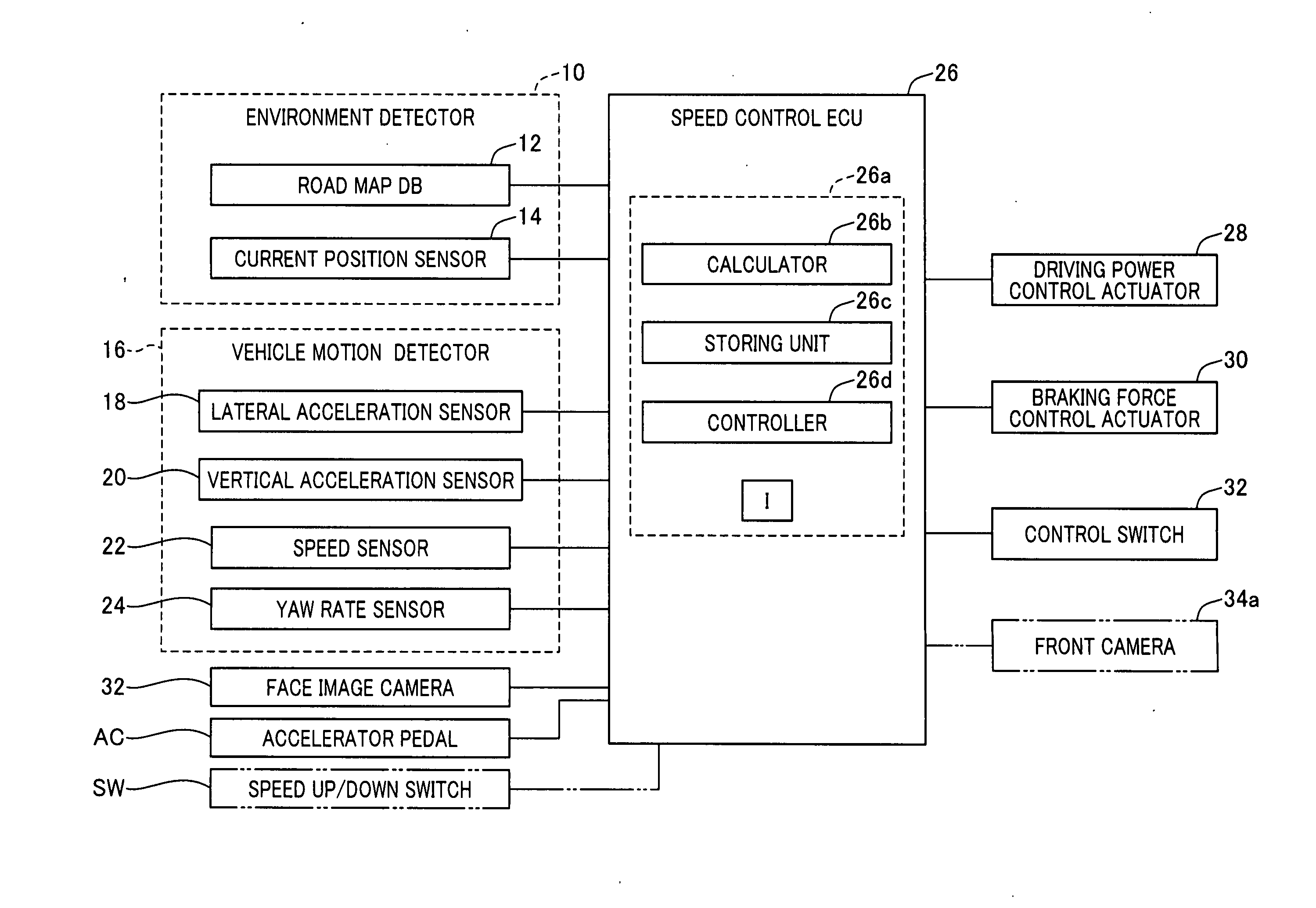
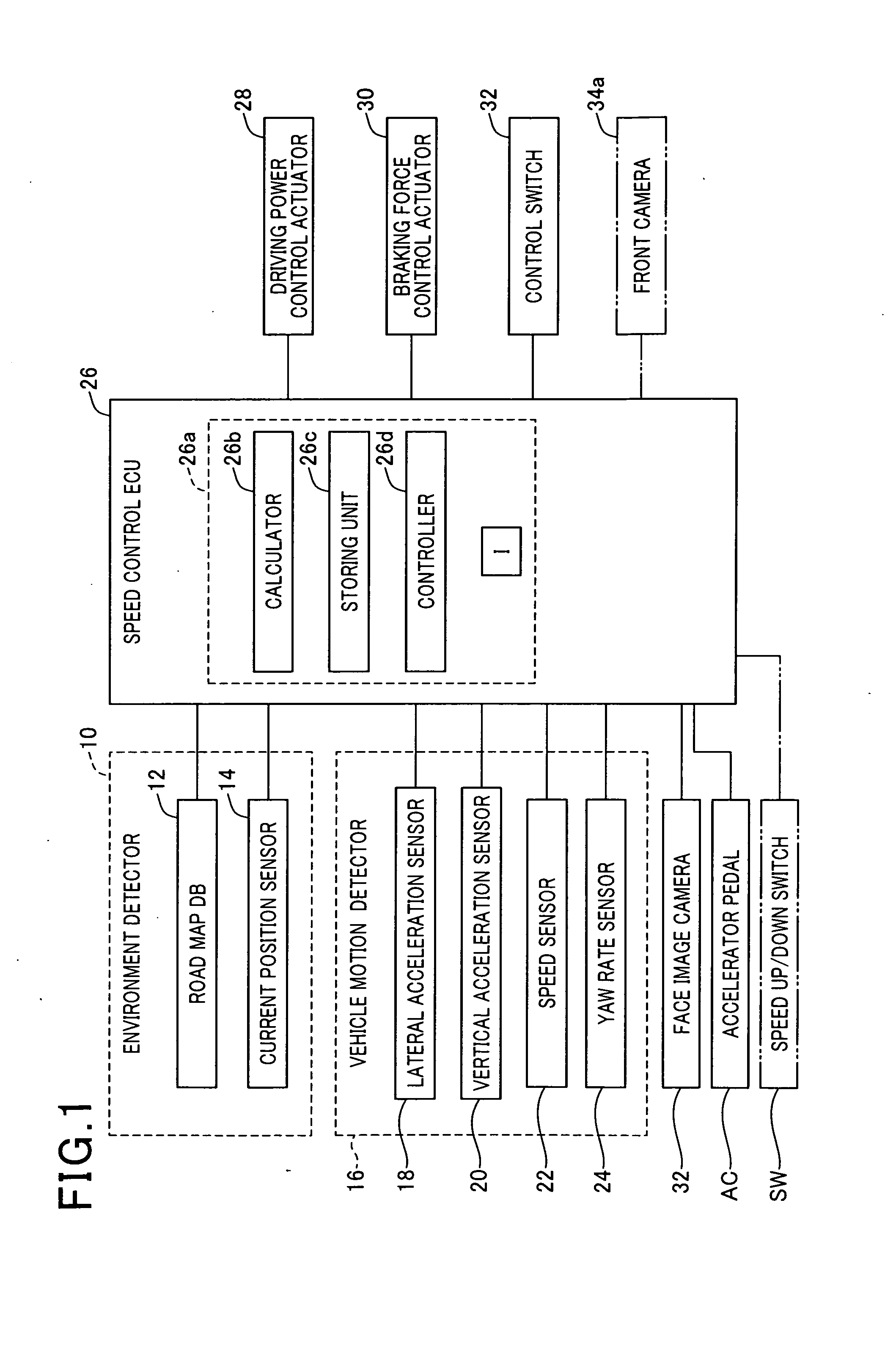
[0034]An example of the structure of an apparatus AP for controlling the speed of a vehicle, such as a motor vehicle, which can run a road according to the present disclosure is illustrated in FIG. 1; this vehicle is an example of various mobile objects.

[0035]The apparatus AP installed in the vehicle includes an environment detector 10, a vehicle motion detector 16, a speed control ECU (Electronic Control Unit) 26, a driving power control actuator 28, a braking control actuator 30, a control switch 32, and a face image camera 34. Each of the elements 10, 16, 28, 30, 32, and 34 is communicably connected with the speed control ECU 26.

[0036]The environment detector 10 includes a road map database 12 and a current position sensor, such as a GPS receiver, 14. The road map database (DB) 12 stores therein data of road map. The current position sensor 14 is operative to det...


PUM


Abstract

In an obtainer for obtaining speed feeling of a driver of a movable object, a gaze point setter sets a gaze point of the driver, and a motion detector detects relative motion of an environmental field around the mobile object with respect to the mobile object. A divergent component calculator projects the relative motion of the environmental field in a coordinate system. The coordinate system is formed by modeling a retina sphere of the driver of the mobile object. The divergent calculator calculates each of divergent components of the projected relative motion of the environmental field radially expanding from the gaze point. A speed feeling calculator calculates speed feeling of the driver based on the divergent components of the projected relative motion of the environmental field radially expanding from the gaze point calculated by the divergent component calculator.

Description

CROSS REFERENCE TO RELATED APPLICATIONS[0001]This application is based on Japanese Patent Application 2010-186413 filed on Aug. 23, 2010. This application claims the benefit of priority from the Japanese Patent Application, so that the descriptions of which are all incorporated herein by reference.TECHNICAL FIELD[0002]The present disclosure relate to apparatuses for controlling the speed of a mobile object.BACKGROUND[0003]Japanese Patent Application Publication No. H05-270368 discloses a speed control system for controlling the speed of a vehicle to automatically keep the speed limit.[0004]The speed control system includes a plurality of transceivers, a receiver, a speed detector, a comparator, and a brake controller. The plurality of transceivers are located on traffic lanes for vehicles. Each of the transceivers transmits a signal associated with the speed limit for vehicles. The receiver is installed in a vehicle to be controlled, and receives the signal transmitted from a transc...

Claims


Application Information

Patent Timeline
Patent Type & Authority Applications(United States)
IPC IPC(8): B60K31/00G06F15/00G05D13/00
CPCA61B3/113A61B5/18B60W30/143B60W2550/402B60W2550/142B60W2550/143B60W2550/30B60W2540/22A61B5/163B60W2552/20B60W2554/80B60W2552/15B60W2556/50G06V40/19G06V20/597
Inventor INOU, HIROSHISAWADA, MAMORUTOTSUKA, SEIJI
Owner DENSO CORP
Why Eureka
Try Eureka