System and method for panel linking in a security system

a security system and system technology, applied in the field of system and method for panel linking in a security system, can solve problems such as putting themselves in unnecessary danger, and achieve the effect of limiting access

Inactive Publication Date: 2010-06-08
ADEMCO INC
View PDF23 Cites 192 Cited by
  • Summary
  • Abstract
  • Description
  • Claims
  • Application Information

AI Technical Summary

Benefits of technology

[0009]In accordance with these and other objects, the present invention is a security system comprising a plurality of security subsystems, or associated security systems, each of the security subsystems being discretely located, typically in separate buildings. The security subsystems are interconnected by a system communications bus to enable bi-directional communication between the security subsystems. Each of the security subsystems comprises a user interface, a control panel, a plurality of security devices, a local communications bus, and a panel linking gateway (PLG). The PLG allows data on the local communications bus of each security subsystem to be transmitted to and received from the low cost system communications bus.
[0014]In order to limit access in the security system, a user must also enter a user identification code when entering the link request code into a user interface. The control panel to be linked verifies permission based on the user identification code and additional information programmed during installation of the security subsystems. The additional information may comprise a list of user ID's that can be linked to a particular partition for the user code entered. This allows different levels of security in different sections of different buildings.

Problems solved by technology

When there is an alarm condition, the security personnel must walk to the building to view the building's keypad to determine type of alarm condition present, thereby putting themselves in unnecessary danger.

Method used


Image

  • System and method for panel linking in a security system
  • System and method for panel linking in a security system
  • System and method for panel linking in a security system

Examples


Embodiment Construction

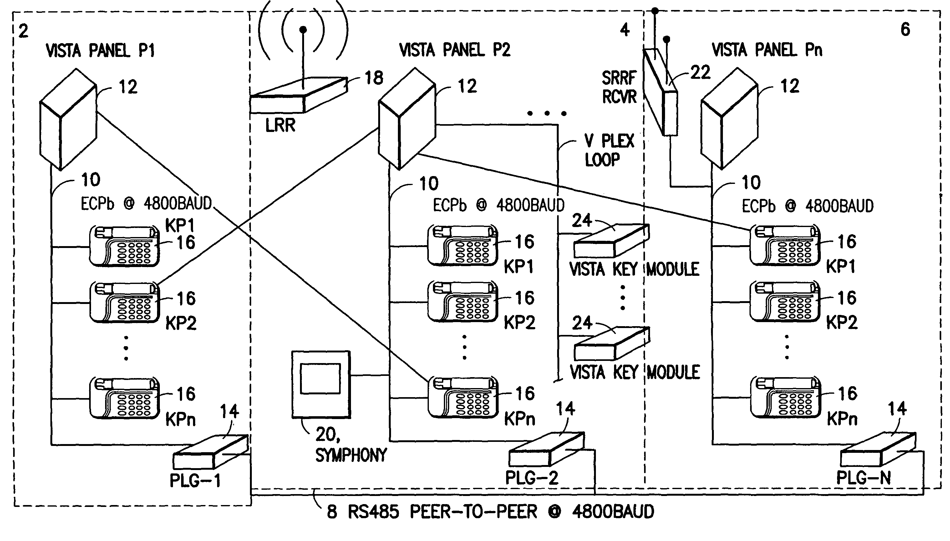
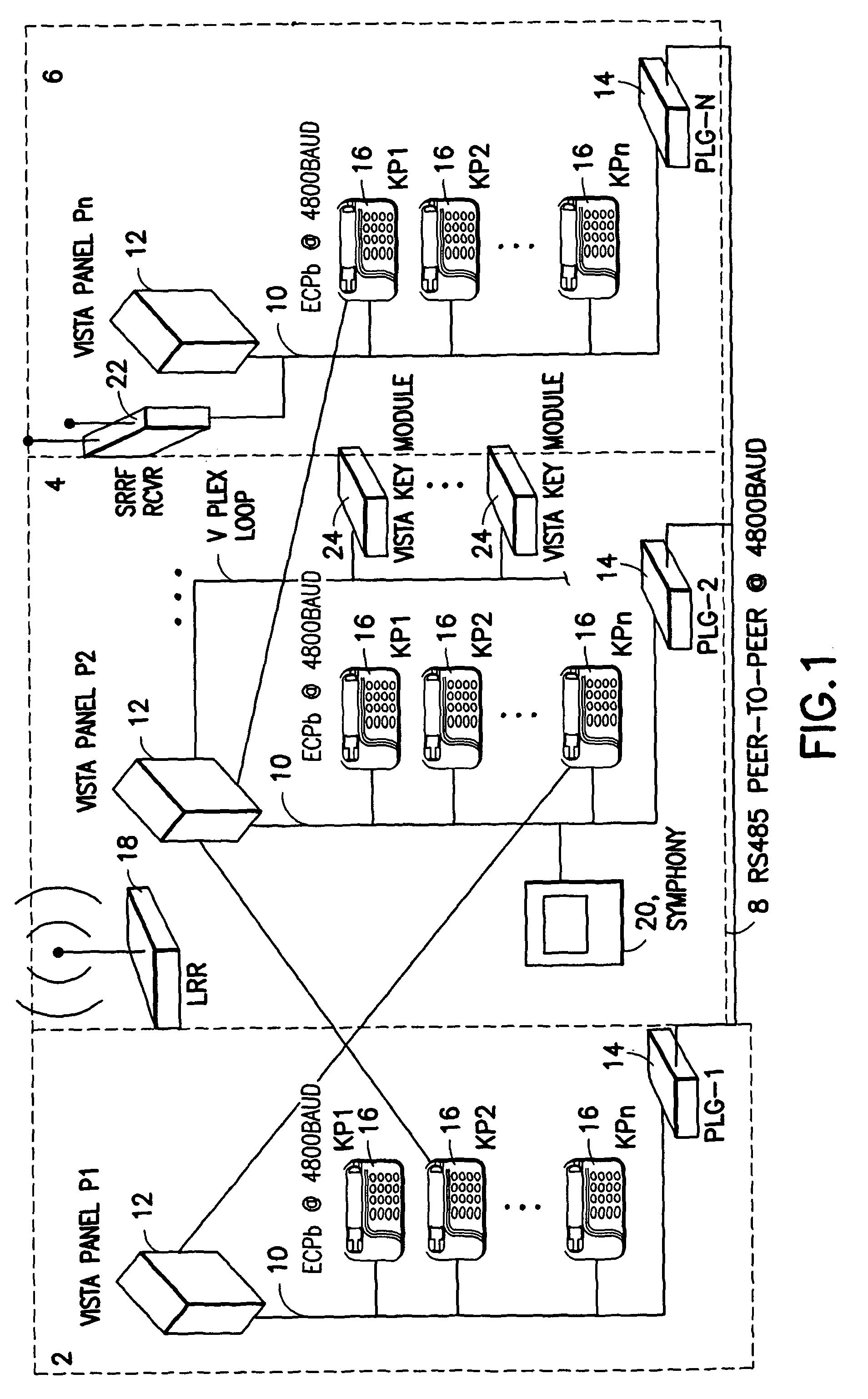
[0022]Referring to FIG. 1, shown is a security system 1 containing three security subsystems 2, 4, and 6. The security subsystems 2, 4, and 6 are connected to each other through communications bus 8, which is an RS485 UART-based, peer-to-peer protocol without clash detection. An RS485 bus is a standard communications bus with a baud rate of 4800 that allows communication over long distances and is well known in the art. Theoretically there may be any number of security subsystems connected to the RS485 bus 8, but only three are shown here. Each security subsystem 2, 4, and 6 contains a panel 12, an ECP bus 10, a panel linking gateway (PLG) 14, and a number of user interfaces including keypads 16, long range radio 18, symphony 20 (a graphical user interface that operates like a keypad but has a touch sensitive screen to control the actions of the panel), short range RF receiver 22, and key modules 24. Each security subsystem 2, 4, and 6, also includes a number of sensors, not shown, ...


PUM


Abstract

A security system comprising a plurality of security subsystems each of the security subsystems being discretely located, typically in separate buildings. The security subsystems are interconnected by a system communications bus to enable bi-directional communication between the security subsystems. Each of the security subsystems comprises a user interface, a control panel, a plurality of security devices, a local communications bus, and a panel linking gateway. The panel linking gateway allows data on the local communications bus of each security subsystem to be transmitted to and received from the system communications bus. The security system allows a keypad or other user interface from one security subsystem to access and control a second remote security subsystem.

Description

CROSS REFERENCE TO RELATED APPLICATION[0001]This application is a continuation application of U.S. application Ser. No. 10 / 099,141, filed on Mar. 13, 2002, now U.S. Pat. No. 6,868,493.BACKGROUND OF THE INVENTION[0002]This invention relates to communication between multiple security systems, and in particular to security systems that allow a keypad from one security system to access and control a number of remote security systems using an established communications bus.[0003]Many companies today occupy a number of buildings in a “campus” or “office complex” type environment, wherein the multiple buildings are within close proximity of each other and monitored for security by a common security office. Typically each building in the complex is secured by its own individual alarm system. These alarm systems are controlled by keypads, consoles, and other user interface devices to allow humans to manage security features such as: arming, disarming, and limiting access within the premises....

Claims


Application Information

Patent Timeline
Patent Type & Authority Patents(United States)
IPC IPC(8): H04L29/00G06F17/30G08B9/00G08B13/22G08B25/14H04L12/46H04L12/66H04L29/06H04M11/04
CPCG08B25/008G08B25/14H04L12/66H04M11/04H04L12/4604G08B25/007
Inventor ORLANDO, ROBERT J.SIMON, SCOTTHOPE, JR., GORDON G.TALLINI, DAMIAN JGOKLEVENT, METIN L.MARINO, FRANCIS C
Owner ADEMCO INC
Why Eureka
Try Eureka