Mobile terminal

a mobile terminal and terminal technology, applied in the direction of antennas, antenna details, electrically short antennas, etc., can solve the problems of increasing the thickness and size of the mobile terminal, and achieve the effect of reducing the size and thickness of the mobile terminal

Inactive Publication Date: 2010-07-06
LG ELECTRONICS INC
View PDF1 Cites 17 Cited by
  • Summary
  • Abstract
  • Description
  • Claims
  • Application Information

AI Technical Summary

Benefits of technology

[0009]Therefore, in order to address the above matters the various features described herein have been conceived. One aspect of the exemplary embodiments is to provide a mobile terminal in which a fastening screw for fastening a terminal casing serves as a connection terminal that electrically connects an antenna mounted on an outer surface of the terminal casing and a printed circuit board (PCB) mounted within the terminal casing, and the length of the fastening screw can be used as a resonance length of the antenna, to thus reducing the size and thickness of the mobile terminal.
[0011]With the additional length of the fastening screws, the external antenna and the internal antenna may then form a total length that corresponds to a resonance frequency bandwidth required for the mobile terminal. Accordingly, the internal antenna itself may have a smaller length and volume, and thus the overall size of the mobile terminal can be made smaller or additional components may be mounted in the mobile terminal due to the space saved by employing the fastening screw as part of the total antenna length.
[0017]The first and second fastening screws may be formed to have respectively different lengths, which allow the length of the connection between the internal antenna and the external antenna to be adjustable, such that signal frequency tuning of the antennas would be possible.

Problems solved by technology

However, such a mobile terminal with the internal antenna has a problem in that because the antenna is installed in the terminal, a space for mounting the antenna should be secured within the terminal, and in this case, the antenna installation position is limited to avoid a frequency interference with other components, resulting in the increase in the thickness and size of the mobile terminal.

Method used


Image

  • Mobile terminal
  • Mobile terminal
  • Mobile terminal

Examples


Embodiment Construction

[0031]The mobile terminal according to exemplary embodiments of the present invention will now be described with reference to the accompanying drawings.

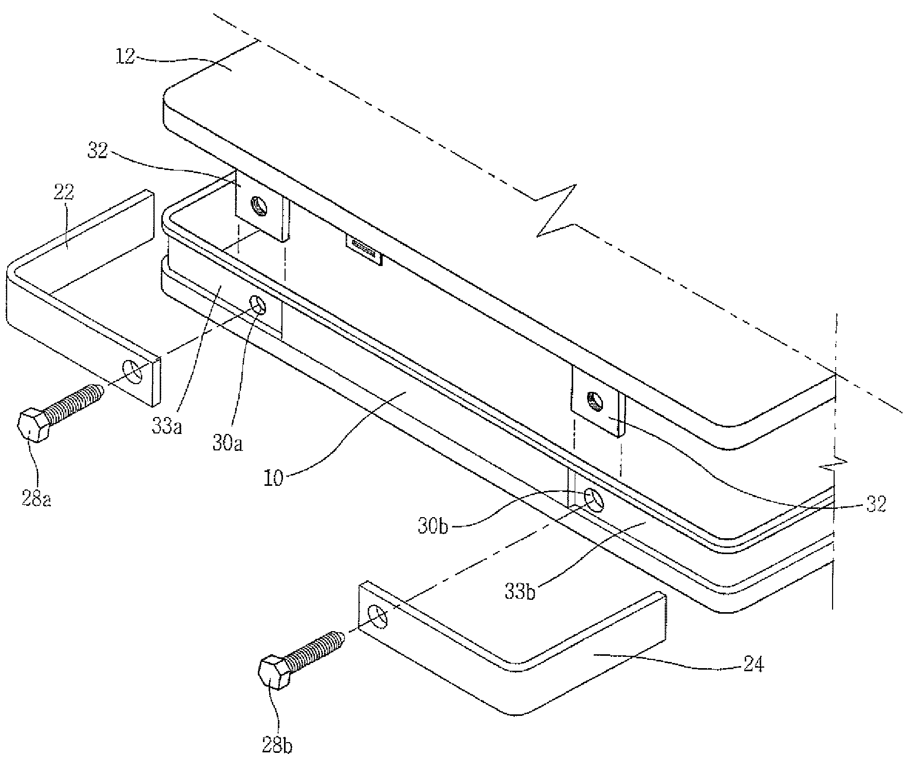
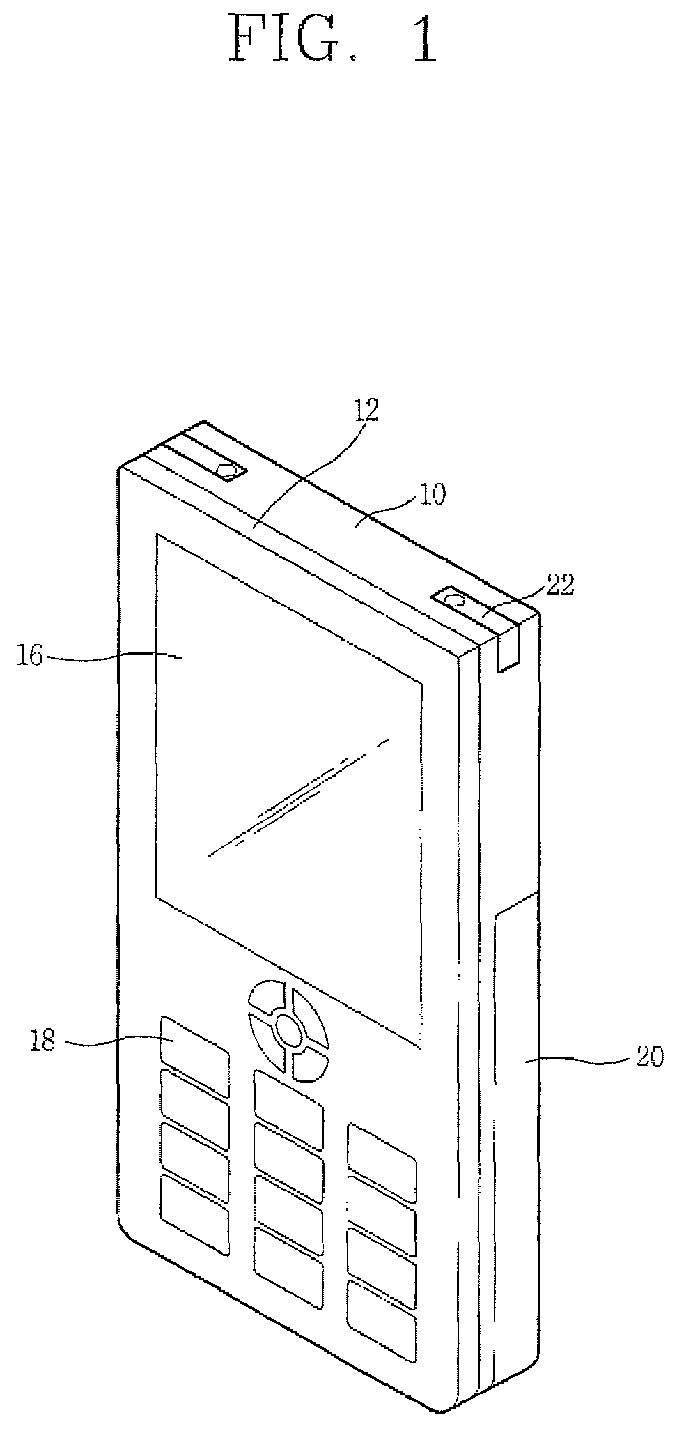
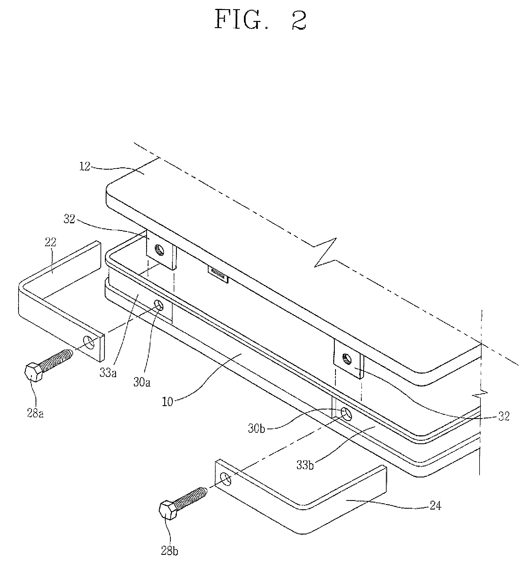
[0032]FIG. 1 is a perspective view of a mobile terminal according to a first exemplary embodiment of the present invention, FIG. 2 is an exploded perspective view of a terminal casing of a mobile terminal according to the first exemplary embodiment of the present invention, and FIG. 3 is a partial sectional view of the mobile terminal according to the first exemplary embodiment of the present invention.

[0033]The mobile terminal according to the first exemplary embodiment of the present invention includes terminal casings 10 and 12, a PCB (Printed Circuit Board) 14 disposed within the terminal casings 10 and 12; a display 16 disposed on a front surface of the terminal casing 12 and displaying information; an input unit 18 disposed on the front surface of the terminal casing 12 and inputting information; a battery 20 mounted on a rear ...


PUM


Abstract

A mobile terminal includes: a terminal casing including a first casing and a second casing combined with the first casing; an external antenna mounted on an external surface of the terminal casing; an internal antenna mounted within the terminal casing; and at least one fastening screw that fastens the first and second casings and electrically connects the external and internal antennas. The size and thickness of the terminal can be reduced.

Description

CROSS REFERENCE TO RELATED APPLICATIONS[0001]This application claims priority to Korean Application No. 10-2007-0002562, filed Jan. 9, 2007, and is herein incorporated by reference in the entirety.BACKGROUND OF THE INVENTION[0002]1. Field of the Invention[0003]The present invention relates to a mobile terminal and, more particularly, to a mobile terminal with a metallic element at an outer surface of a terminal casing that can be used as an antenna.[0004]2. Description of the Related Art[0005]Recently, a mobile terminal with an internal antenna, in which an antenna that transmits or receives radio signals is installed, rather than being protruded to outside of the mobile terminal, to make the mobile terminal aesthetically fine, is widely used.[0006]However, such a mobile terminal with the internal antenna has a problem in that because the antenna is installed in the terminal, a space for mounting the antenna should be secured within the terminal, and in this case, the antenna instal...

Claims


Application Information

Patent Timeline
Patent Type & Authority Patents(United States)
IPC IPC(8): H01Q1/24
CPCH01Q1/242H01Q9/145H01Q1/243H04B1/38
Inventor KIM, JUNG-HA
Owner LG ELECTRONICS INC
Why Eureka
Try Eureka