Non-aqueous electrolyte cell and solid electrolyte cell

a solid electrolyte and electrolyte technology, applied in the direction of cell components, final product manufacturing, sustainable manufacturing/processing, etc., can solve the problems of increasing the toxicity of cathode active materials, affecting so as to reduce internal shorting, improve the cyclic characteristics of the cell, and maintain constant electrical capacity

Inactive Publication Date: 2007-08-14
MURATA MFG CO LTD
View PDF7 Cites 14 Cited by
  • Summary
  • Abstract
  • Description
  • Claims
  • Application Information

AI Technical Summary

Benefits of technology

[0010]It is therefore an object of the present invention to provide a non-aqueous electrolyte cell and a solid electrolyte cell that, with LixFe1-yMyPO4 as the cathode active material, suppresses internal shorting thereby improving the cyclic characteristics of the cell. It is a further object of the invention to provide a cell having constant electrical capacity and a reduced size and thickness than prior cells. Finally, a high capacity cell having a fixed outer shape is also provided.
[0013]The outermost portion of the cathode that faces the interior surface of the cell casing or exterior material does not contribute to cell reaction in the non-aqueous electrolyte cell or the solid electrolyte cell of the present invention. Furthermore, the spiral formation of the cell causes the innermost portion of the anode, located within the core of the cell, to face itself thereby providing two surfaces of the same polarity that do not contribute to cell reaction. The spiral formation in conjunction with the exposed portions of the anode and cathode current collectors wherein those portions do not contribute to cell reaction combine to resist the stress applied thereto by repeatedly charging and discharging the cell and, because no active material is present on the exposed portions of the cathode and anode, there is no risk of the active material becoming detached and falling off. Accordingly, internal shorting is prevented and the cyclic characteristics of the cell of the present invention are improved. Moreover, according to the present invention, since the active material not contributing to cell reaction is not deposited on the current collector, the outer size or thickness of the cell is reduced, or the amount of the active material contributing to the cell reaction can be increased, with the outer shape of the cell remaining unchanged, thus enabling a high electrical capacity.

Problems solved by technology

However, these cathode active materials, containing metal elements of low Clark number in their composition, suffer from high cost and difficulties met in connection with supply in stability.
Moreover, these cathode active materials are higher in toxicity and have a significant negative effect on the environment.
However, when LixFe1-yMyPO4 is used as the cathode active material, and charging / discharging of the cell is carried out repeatedly, the charging / discharging capacity of the cell is decreased appreciably due to internal shorting.
In addition, those portions of the cathode and anode that do not contribute to cell reaction are also subjected to stress caused by the volumetric changes in the cell-reaction portions of the cathode and anode.
This stress can result in the detachment of the active materials from the cathode and anode current collectors.
This detachment, in turn, causes internal shorting of the cell device.
These high volumetric changes can also create larger stress on those portions of the cathode and anode that do not contribute to the cell reaction resulting in a substantial increase of internal shorting occurrences.
Thus, optimum cell cyclic characteristics cannot be achieved when LixFe1-yMyPO4 is used as the cathode active material.

Method used


Image

  • Non-aqueous electrolyte cell and solid electrolyte cell
  • Non-aqueous electrolyte cell and solid electrolyte cell
  • Non-aqueous electrolyte cell and solid electrolyte cell

Examples


example 1

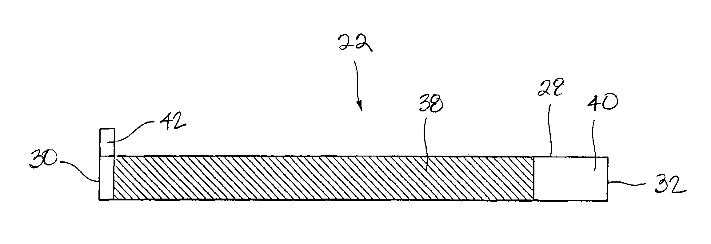
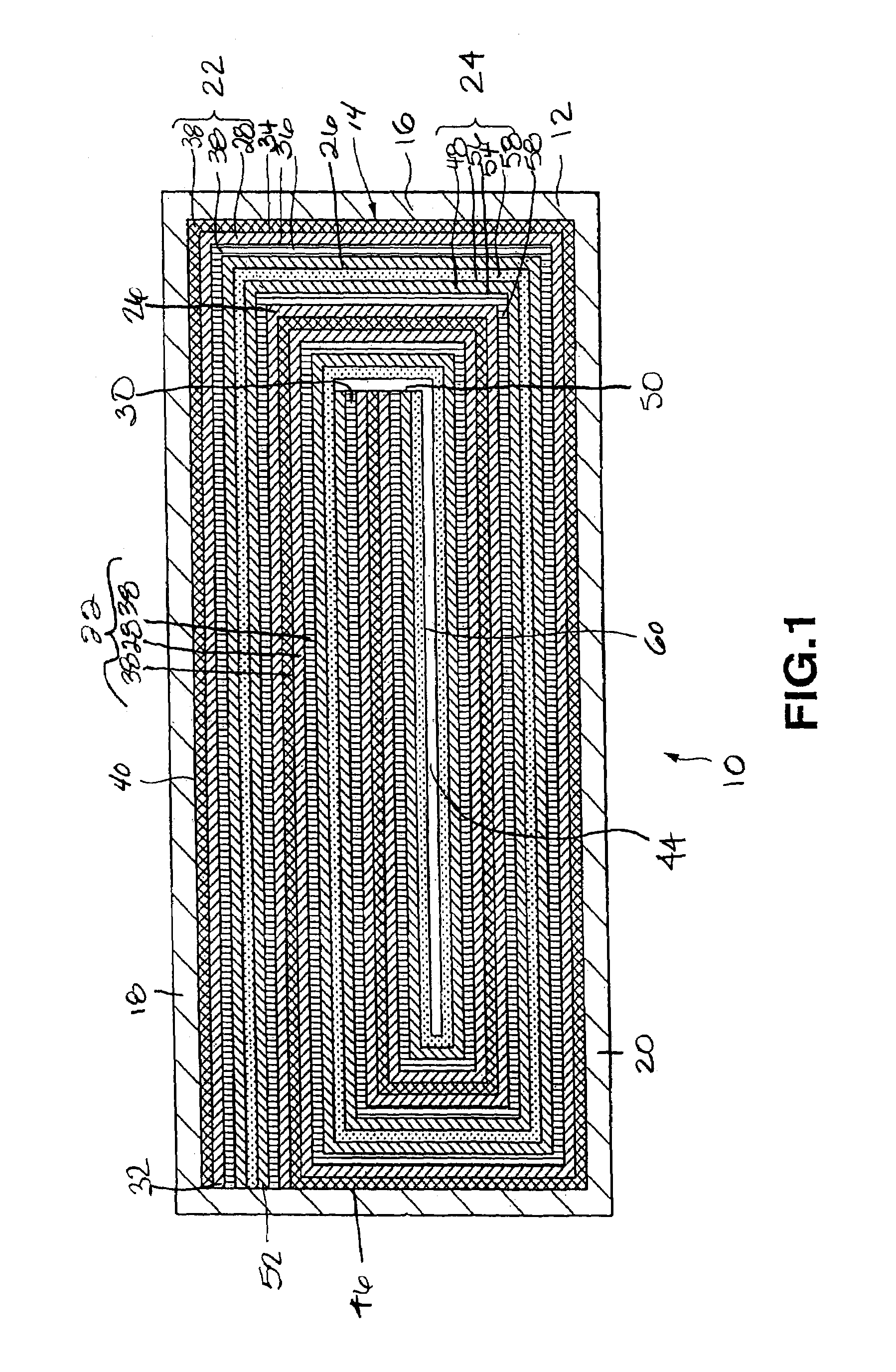
[0056]A cell was prepared under the same conditions as those for the cell of Comparative Example 1, except that the coating thickness on one face of the cathode current collector was 64.5 μm, the coating thickness on one face of the anode current collector was 48.5 μm, and the coating length of the cathode active material on the outer face of the cathode current collector, at the time of winding, was 23 cm from the cathode beginning end so that the total thickness of the layered and coiled cathode, anode and separator was 3.11 mm as in the cell of Comparative Example 1. In the cell of the present Example 1, the portion of the cathode current collector lying on the radially outermost periphery and facing the inner surface of the walls of the cell can, that is, the outer face of the current collector near the terminating end of the cathode current collector, is provided with a current collector exposing portion that is not coated with the cathode active material.

example 2

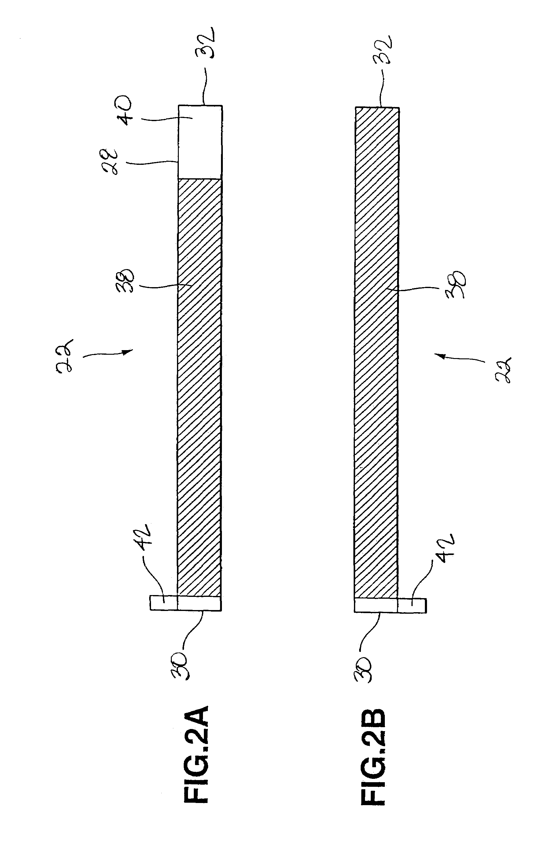
[0057]A cell was prepared under the same conditions as those for the cell of the Comparative Example 1, except that the coating thickness of the cathode active material on one face of the cathode current collector was 65 μm, the coating thickness of the anode active material on one face of the anode current collector was 49 μm, and the coating length of the cathode active material on the inner face of the cathode current collector, at the time of winding, was 24 cm measured from the terminating end of the cathode current collector thereby providing a total thickness of 3.11 mm as in the cell of Comparative Example 1. In the cell of the present Example 2, however, the inner face of the anode current collector lying in the core or innermost portion of the cell toward the beginning end of the current collector wherein the inner face of the anode current collector faces itself is provided with a current collector exposing portion not coated with the anode active material.

example 3

[0058]A cell was prepared under the same conditions as those for the cell of the Comparative Example 1, except that the coating thickness of the cathode active material on one face of the cathode current collector was 70.5 μm, the coating thickness of the anode active material on one face of the anode current collector was 53 μm, the coating length of the cathode active material on the outer face of the cathode current collector, at the time of winding, was 23 cm measured from the beginning end of the cathode current collector, and the coating length of the anode active material on the inner face of the anode current collector, at the time of winding, was 24 cm measured from the terminating end of the anode current collector, so that the total thickness of the cell device will be 3.11 mm as in the cell of Comparative Example 1. In the cell of the present Example 3, however, the outer face of the cathode current collector lying at the radially outermost periphery of the cell device f...


PUM

PropertyMeasurementUnit
densityaaaaaaaaaa
specific surface areaaaaaaaaaaa
particle sizeaaaaaaaaaa

Abstract

A non-aqueous electrolyte cell is provided having improved cell characteristics and which maintains a cell shape encapsulated in a laminate film even when overdischarged to a cell voltage of 0 V. The cell includes an anode, an electrolyte, and a cathode containing a compound having the formula LixFe1-yMyPO4, wherein 0.05≦x≦1.2 and 0≦y≦0.8, and wherein M is at least one element selected from the group consisting of Mn, Cr, Co, Cu, Ni, V, Mo, Ti, Zn, Al, Ga, Mg, B and Nb. Exposed portions of an anode current collector and a cathode current collector prevent internal shorting of the cell.

Description

RELATED APPLICATION DATA[0001]The present application claims priority to Japanese Application(s) No(s). P2000-306877 filed Oct. 5, 2000, which application(s) is / are incorporated herein by reference to the extent permitted by law.BACKGROUND OF THE INVENTION[0002]This invention relates to a non-aqueous electrolyte cell and to a solid electrolyte cell. More particularly, it relates to a cathode and an anode representing cell components of a non-aqueous electrolyte cell and a solid electrolyte cell. Recently, with drastic progress in the art of electronic equipment, investigations into rechargeable secondary cells, as a power source usable conveniently and economically for prolonged period of time, are proceeding briskly. Known secondary cells include lead storage cells, alkali storage cells, and non-aqueous electrolyte secondary cells. A particular non-aqueous electrolyte secondary cell, namely, a lithium-ion secondary cell possesses certain advantages over other types of secondary cel...

Claims


Application Information

Patent Timeline
Patent Type & Authority Patents(United States)
IPC IPC(8): H01M4/58H01M2/14H01M4/62H01M10/05H01M6/10H01M10/0525H01M10/0562H01M10/0565H01M10/0566H01M10/0587
CPCH01M4/136H01M4/5825H01M10/0525H01M10/0565H01M10/0587Y02E60/122H01M10/058H01M4/48Y02E60/10Y02P70/50
Inventor TAKAHASHI, KIMIOHOSOYA, MAMORUMIYAKE, MASAMI
Owner MURATA MFG CO LTD
Why Eureka
Try Eureka