Portable terminal having a plurality of hinged housing sections

a portable terminal and hinged housing technology, applied in the direction of coupling device connection, instruments, horology, etc., can solve the problems of increasing the number of components, increasing the thickness of the pcb, and limited pcb siz

Inactive Publication Date: 2006-11-23
SAMSUNG ELECTRONICS CO LTD
View PDF10 Cites 15 Cited by
  • Summary
  • Abstract
  • Description
  • Claims
  • Application Information

AI Technical Summary

Benefits of technology

[0018] In accordance with another aspect of the present invention, there is provided a portable terminal having various components mounted thereon. The terminal includes: a plurality of PCBs having components corresponding to each function of the terminal mounted thereon, respectively, and bei...

Problems solved by technology

As a result, the number of components increases while the PCB's size is limited by the small size of the portable terminal.
Therefore, as more functions are added to the portable terminal, the PCB's thickness inevitably increases.
Although PCB size may be reduced, not all components can be mounted in this manner.
This is an obstacle to making the terminals in a compact size.
Further, as the terminals become thicker and larger due to the bulky PCB, they must be carried in pockets, in separate bags, o...

Method used


Image

  • Portable terminal having a plurality of hinged housing sections
  • Portable terminal having a plurality of hinged housing sections
  • Portable terminal having a plurality of hinged housing sections

Examples


first embodiment

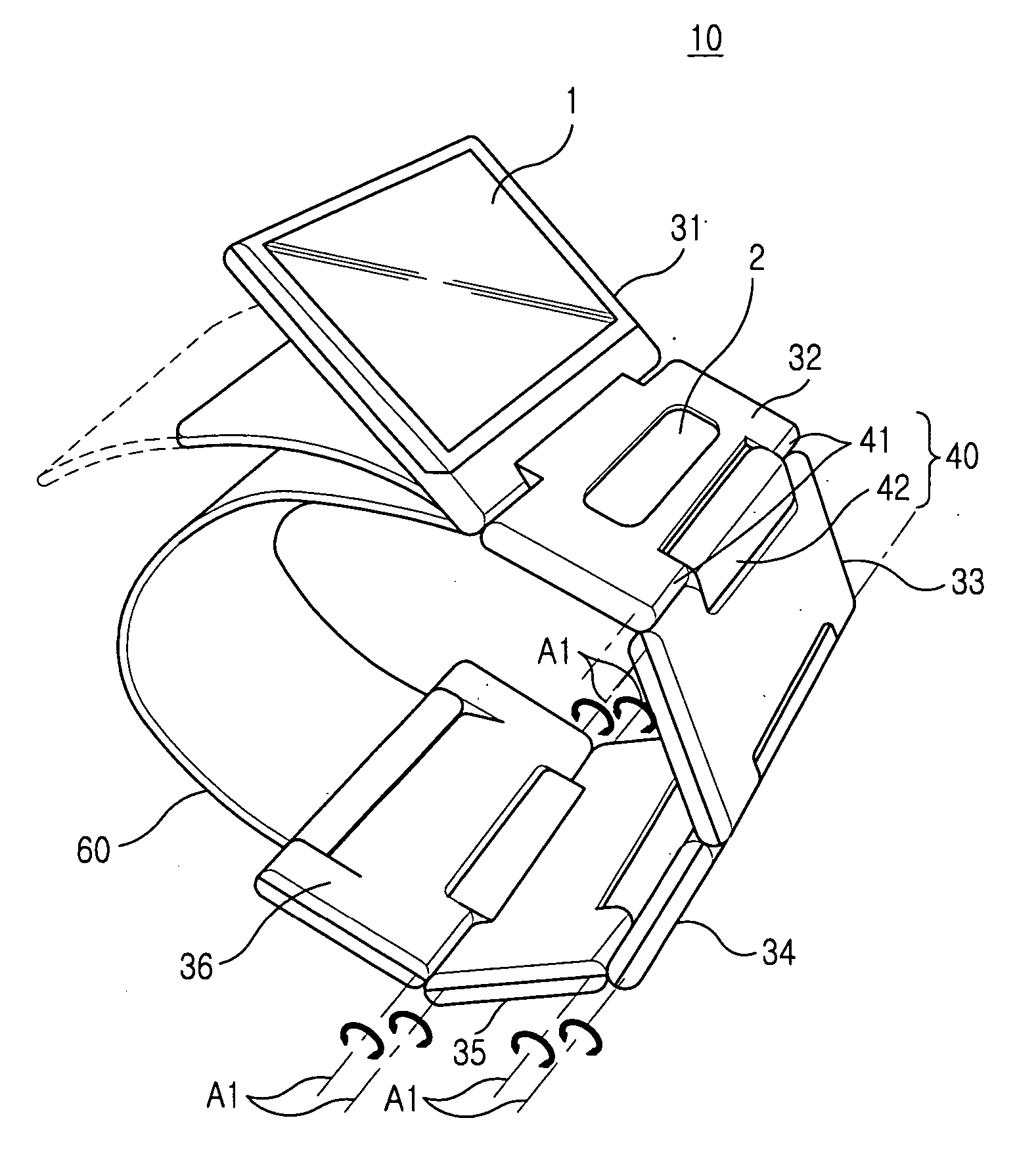
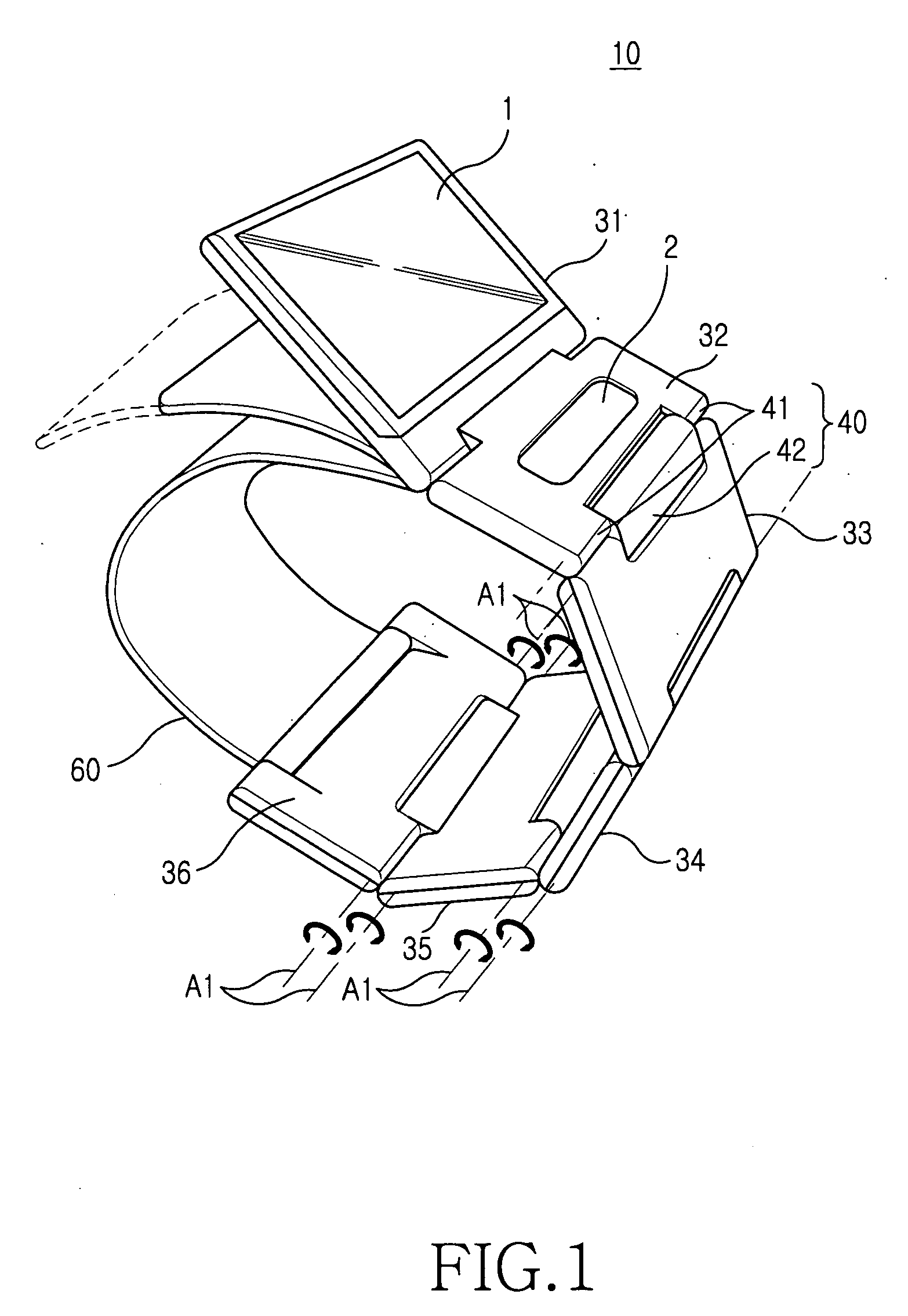
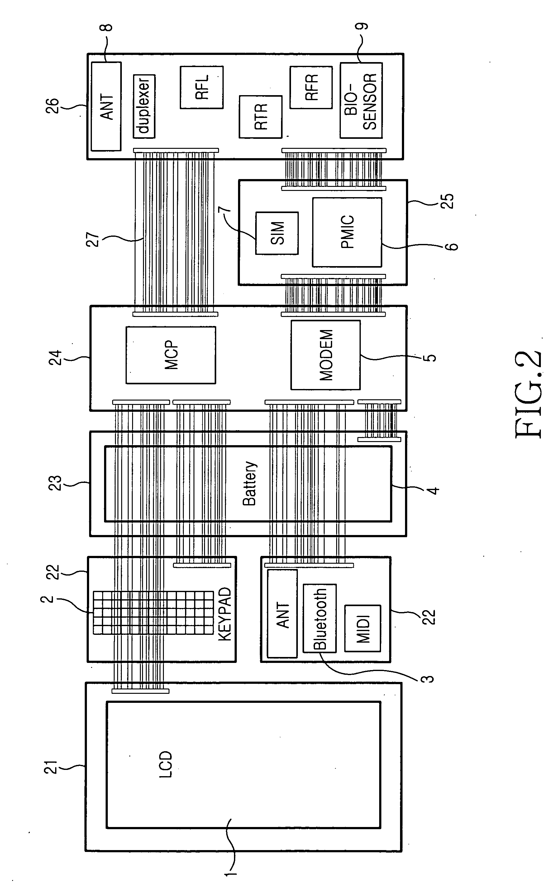
[0029]FIG. 1 is a perspective view illustrating a portable terminal according to the present invention. Referring to FIG. 1, a portable terminal 10 includes at least one housing section 31-36, each housing section containing its own PCB 21-26 (shown in FIG. 2) and at least one hinge device 40. The PCBs 21-26 have respective components mounted thereon, which correspond to each function of the terminal. Additionally, the PCBs 21-26 are connected to each other.

[0030] The hinge devices 40 are positioned on the connections between the respective housing sections 31-36 and enable the housing sections 31-36 to rotate and bend relative to each other, such that the portable terminal 10 can be easily worn on a user's body, e.g., wrist.

[0031] Referring to FIGS. 1 and 2, the first housing section 31 contains the first PCB 21, which has an LCD 1 mounted thereon, and is connected to the second housing section 32 by one of the hinge devices 40 in such a manner that it can rotate and bend relative...

second embodiment

[0042]FIG. 6 is a perspective view illustrating a portable terminal according to the present invention and FIG. 7 is a perspective view magnifying part A illustrated in FIG. 6. Referring to FIGS. 6 and 7, the portable terminal has housing sections 30, which separately contain a PCB 20. The PCBs 20, on which components corresponding to each function of the terminal are mounted, are contained in each housing sections 30 and are electrically connected to one another.

[0043] The housing sections 30 are inserted into and mounted on tube housings 100, respectively, as illustrated in FIG. 6. More specifically, each tube housings 100 has an insertion hole 102 formed therein, into which a housing sections 30 is inserted.

[0044] As illustrated in FIG. 6, the tube housing 100 has at least one connection portion, which is connected to the lateral surface thereof and has a bending groove 101 so that the tube housing 100 can bend relative to a connected tube housing.

[0045] When the user wants to ...


PUM


Abstract

A portable terminal having a number of housing sections that rotate and bend relative to one another while containing their own PCBs to be easily worn on the user's body. The portable terminal includes various components mounted thereon and includes a plurality of PCBs having the components corresponding to each function of the terminal mounted thereon, while being electrically connected to one another, a plurality of housing sections that each contain one of the PCBs, and hinge devices for connecting the housing sections.

Description

PRIORITY [0001] This application claims priority under 35 U.S.C. § 119 to an application entitled “Portable Terminal” filed with the Korean Intellectual Property Office on May 18, 2005 and assigned Serial No. 2005-41508, the contents of which are incorporated herein by reference. BACKGROUND OF THE INVENTION [0002] 1. Field of the Invention [0003] The present invention relates generally to a portable terminal, and more particularly to a portable terminal having a number of housings including their own PCBs. [0004] 2. Description of the Related Art [0005] In general, portable terminals are tending to be more highly sensitive, compact, and lightweight, in line with the overall trend of electronic components. In addition to the common types of mobile terminals, i.e., bar-type, flip-type, folder-type, etc., wearable terminals, which are worn by a user one their body or clothes, have been developed, e.g., a watch-type terminal that is worn around a user's wrist. [0006] Recently, portable ...

Claims


Application Information

Patent Timeline
IPC IPC(8): H01R13/502
CPCG04G17/083H04M1/0247H04M1/0214H04B1/385H04B1/40
Inventor SIM, DAE-HYUNLEE, KANG-HOONLEE, CHEONG-SUN
Owner SAMSUNG ELECTRONICS CO LTD
Why Eureka
Try Eureka