Positioning and clamping device and positioning device

a clamping device and positioning device technology, applied in the direction of manufacturing tools, metal-working machine components, shaping tools, etc., can solve the problems of increasing production costs, affecting the machining accuracy of workpieces, and the number of parts, so as to facilitate the elastic deformation of the engaging mechanism, increase accuracy, and appropriate rigidity

Active Publication Date: 2010-10-26
PASCAL ENG
View PDF8 Cites 20 Cited by
  • Summary
  • Abstract
  • Description
  • Claims
  • Application Information

AI Technical Summary

Benefits of technology

[0019]The engaging mechanism has a tapered ring portion that makes a face contact with the annular tapered surface, and multiple ribs extending outward, radially, from the tapered ring portion. When the clamping object is pulled down and clamped to the base by the clamping mechanism, the spaces created on the outer side of the tapered ring portion between the multiple ribs facilitate the elastic deformation of the engaging mechanism, and the multiple ribs are compressively elastically deformed, whereby the entire tapered ring portion is enlarged. Therefore, it is ensured that the engaging mechanism is elastically deformed outward, radially, in engagement with the cylindrical shaft, and the tapered ring portion is pressed against the annular tapered surface of the cylindrical shaft. Particularly, the multiple ribs provide appropriate rigidity to the engaging mechanism. If the engaging mechanism is engaged with the cylindrical shaft for the clamping mechanism to pull down and clamp the clamping object to the base, without the central axes of the cylindrical shaft and annular engagement member being aligned, the central axes of the cylindrical shaft and annular engagement member are aligned as a result of the engagement before the engaging mechanism is elastically deformed. In this case, the engaging mechanism is elastically deformed and pressed against the annular tapered surface.
[0020]Consequently, a heavy clamping object can be positioned relative to the base with increased accuracy. With the engaging mechanism being formed integrally with the annular engagement member, the number of parts is decreased. Further, the large elastic deformation amount allows for increased production error tolerance. Therefore, production costs can be reduced. In addition, abrasion that adversely affects the positioning accuracy is reduced, functional deterioration due to machining oil and cutting powder associated with machining is prevented, and high positioning accuracy is maintained for prolonged and repeated use.
[0022]In the positioning mechanism of this positioning and clamping device, an annular tapered surface having a decreasing diameter toward the axial tip of the cylindrical shaft is formed on the inner periphery of the annular engagement member, and an engaging mechanism is formed on the outer periphery side portion of the cylindrical shaft to engage with the annular tapered surface. When the clamping object is pulled down and clamped to the base, the annular engaging mechanism is elastically deformed inward, radially, for radial contraction, and pressed against the annular tapered surface. The engaging mechanism has a tapered ring portion that makes a face contact with the annular tapered surface and multiple ribs extending inward, radially, from the tapered ring portion. The spaces created on the inner side of the tapered ring portion between the multiple ribs facilitate the elastic deformation of the engaging mechanism. The multiple ribs are compressively elastically deformed and the entire tapered ring portion is contracted, whereby it is ensured that the engaging mechanism is elastically deformed for radial contraction. For the rest, the same advantages and efficacy as the invention described above can be obtained.
[0024]When the power output member is moved away from the clamping object by the clamping drive means, with the annular engagement member attached to the clamping object being fitted on the cylindrical shaft attached to the base, the multiple steel balls held in the cylindrical shaft are pushed outward, radially, by the power output member, and make a face or line contact with the multiple engagement recesses, respectively, whereby the clamping object is pulled down and clamped to the base. In this state, when the power output member is moved toward the clamping object by the unclamping means, the multiple steel balls are retracted inward, radially, and disengaged from the multiple engagement recesses of the annular engagement member, whereby the clamping object can be unclamped from the base. In the clamped state, a significantly large force is applied to the engagement recesses with which the steel balls are engaged, and the steel balls are in a face, or line contact with the respective engagement recesses. Compared with a point contact, the steel balls have a larger contact area with the engagement recesses, and the engagement recesses do not have even a trace of contact with the steel balls, so that stable clamping can be maintained for prolonged and repeated use.

Problems solved by technology

An error in positioning the work pallet relative to the table affects the machining accuracy of the work piece.
However, the devices of Patent Documents 1 to 3 have the following problems:
The structure having such a tapered collet increases the number of parts, thereby increasing production costs.
Repeated use of the clamping device causes the cylindrical shaft and tapered collet to wear out at the sliding part, and, further, accumulated abrasion powder may significantly reduce positioning accuracy.
In addition, there is a small gap between the cylindrical shaft and the tapered collet, thus machining oil and cutting powder entering that gap may significantly reduce positioning accuracy.
Therefore, it is difficult for the tapered cone to be elastically deformed for radial contraction.
In other words, its radial contraction is so small that the tapered cone and tapered socket has to be produced with high production accuracy in order for the surface of the tapered socket to abut the receiving tapered surface of the tapered cone, which makes the entire device expensive.
However, upon receiving such a significant force, the annular tapered surface of the tapered cone tends to partially wear out, failing to ensure prolonged positioning accuracy.
Further, when the tapered cone is subject to large elastic deformation for radial contraction, the elastic part experiences excessive stress.
However, if the engaging mechanism is engaged with the cylindrical shaft for pulling down and clamping the pallet to the base before the central axes of the cylindrical shaft and bushing are not aligned (for example with a slight misalignment), the engaging mechanism is, as a result of the engagement, subject to localized elastic deformation, and pressed against the annular tapered surface without the central axes of the cylindrical shaft and bushing being aligned.
In other words, when the pallet carries a heavy load, the pallet may not be reliably or highly accurately positioned in the horizontal direction relative to the base.
Therefore, particularly when a significant clamping force is applied, the steel balls may form trace of point contact on the annular tapered surface, subsequently, receives an uneven clamping force as the pallet is used repeatedly.
It may therefore become difficult to maintain stable clamping.
In such cases, the steel balls can be increased in size or number, however, such attempts result in enlarging the clamping device and are disadvantageous in terms of production cost.
When the devices of Patent Documents 1 to 3 are used, the same problems, as described above, occur.

Method used


Image

  • Positioning and clamping device and positioning device
  • Positioning and clamping device and positioning device
  • Positioning and clamping device and positioning device

Examples


Embodiment Construction

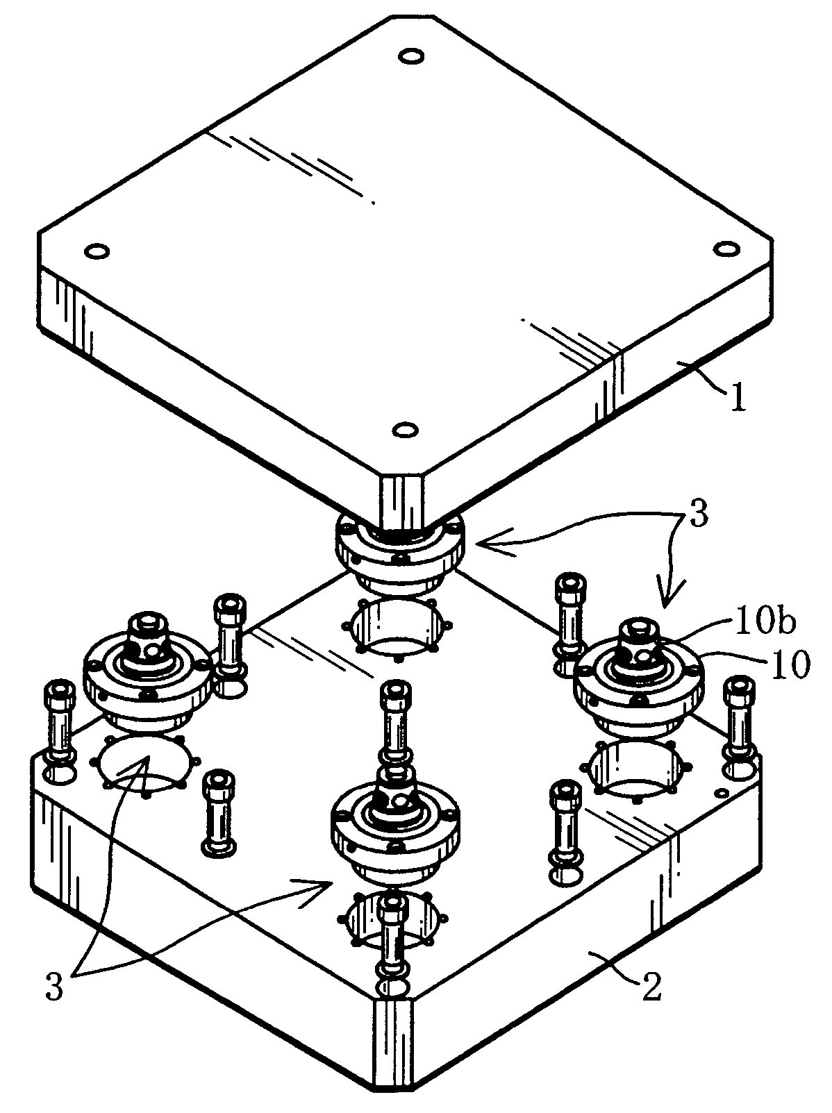
[0042]The best mode for putting this invention into practical use are described hereafter, with reference to the drawings. As shown in FIG. 1, a work pallet 1 (a clamping object), on which a work piece to be machined is fitted, is positioned and clamped to a base member 2, fixed to the table of a machining tool by means of four sets of positioning and clamping devices 3. Then, the work piece on the pallet 1 is machined. Pallet 1 is made of a nearly square thick plate, and base 2 is made of also a nearly square thick plate. Base 2 can be the table of a machining tool. The four sets of positioning and clamping devices 3 are provided in the four corners of the square pallet 1 and base 2.

[0043]The positioning and clamping device 3 will be described next.

[0044]The four sets of positioning and clamping devices 3 have the same structure; therefore, only one of positioning and clamping devices 3 is described.

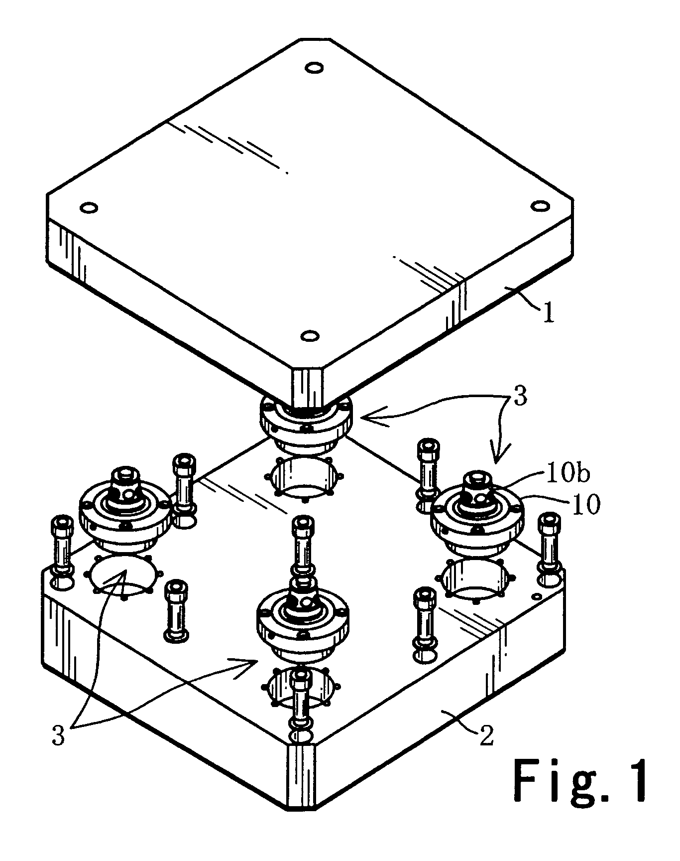
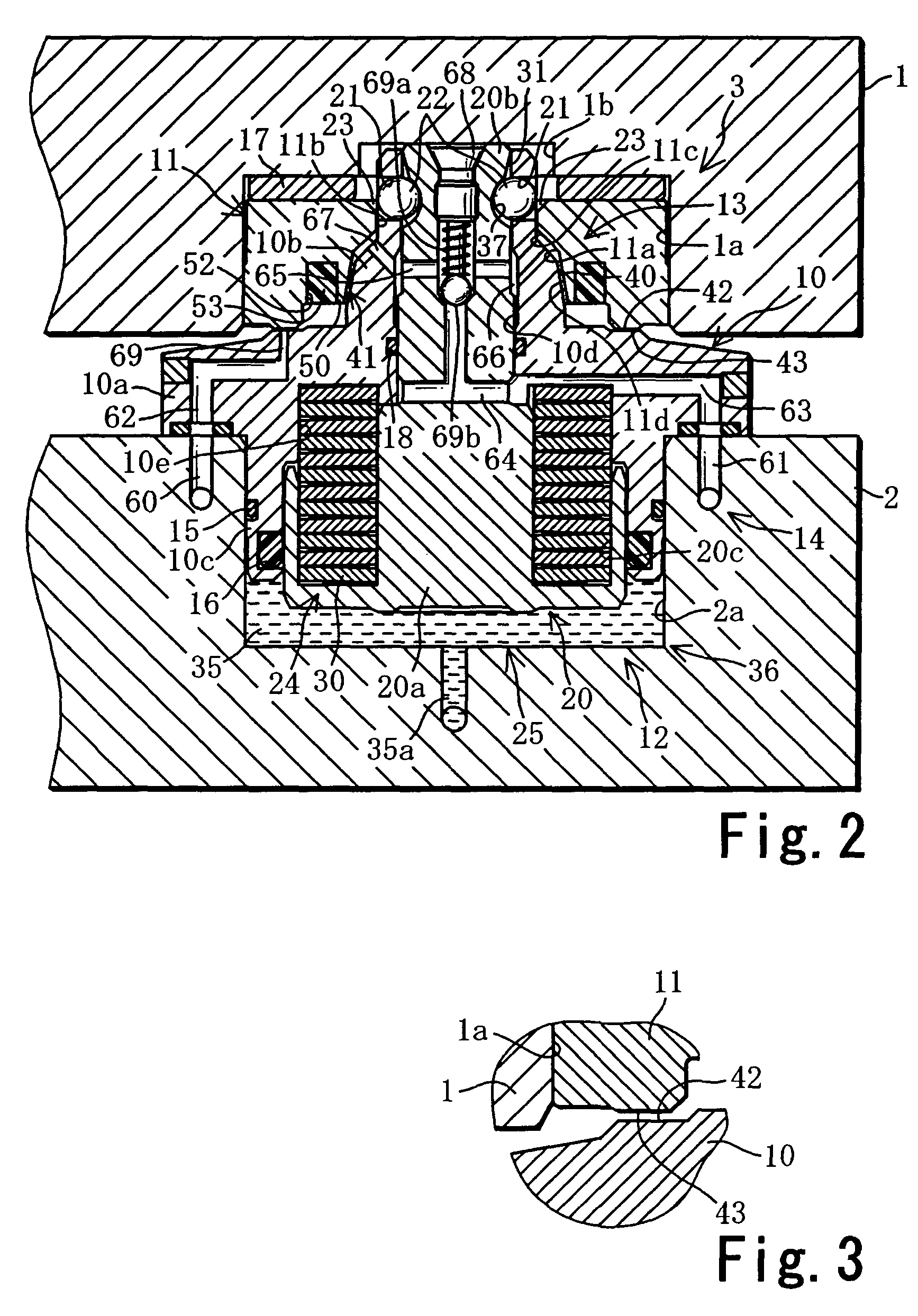
[0045]As shown in FIGS. 2, 4, and 6, the positioning and clamping device 3 comprise...


PUM


Abstract

A positioning mechanism in a positioning and clamping device includes an annular tapered surface that is formed on an outer periphery of a cylindrical shaft for positioning a pallet in the horizontal direction, and has a decreasing diameter toward an axial tip of the cylindrical shaft. An annular engaging mechanism, which is formed on an inner periphery side portion of an annular engagement member, is engageable with the annular tapered surface, and is elastically deformed in the radial direction, as a result of engagement with the annular tapered surface. The engaging mechanism has a tapered ring portion, which makes a face contact with the annular tapered surface, and multiple ribs extending outward, radially, from the tapered ring portion.

Description

TECHNICAL FIELD[0001]The present invention relates to a positioning and clamping device for positioning and clamping a clamping object to a base, and a positioning device for positioning a clamping object relative to a base member.BACKGROUND OF THE RELATED ART[0002]Patent Document 1: Japanese Laid-Open Patent Application No. 2001-38564;[0003]Patent Document 2: Japanese Laid-Open Patent Application No. H08-155770;[0004]Patent Document 3: Japanese Laid-Open Patent Application No. 2003-39264.[0005]In general, a machining tool, such as a machining center, has a machining table. A work pallet is positioned and clamped to the machining table, and a work piece clamped on the work pallet is machined. Some of precision machinery components require a machining accuracy of approximately 1 μm. An error in positioning the work pallet relative to the table affects the machining accuracy of the work piece. In other words, the positioning accuracy of the pallet relative to the table is extremely im...

Claims


Application Information

Patent Timeline
Patent Type & Authority Patents(United States)
IPC IPC(8): B23Q3/14B21D37/14B23Q1/00B23Q3/00B23Q3/06B23Q3/18
CPCB23Q1/0081B23Q3/183B23Q3/00B23Q3/06B23Q3/18
Inventor KURODA, TAKAYUKIMUNECHIKA, TAKAYUKI
Owner PASCAL ENG
Why Eureka
Try Eureka